


|
|
Helical Resonator Notch FilterI have been experimenting with a compact Helical Resonator Notch Filter since discovering by accident that when a transmission line was brought near to a high-Q resonator, a notch was introduced at the resonant frequency. Note that this is not a band-pass filter, but one which introduces a sharp attenuation of unwanted signals around a certain frequency. RequirementIn the UK, there are very strong pager-type signals very near to the weather satellite transmission band (137-138MHz). This has two effects:
My own measurements at this location have shown that a relatively small amount of attenuation of the interfering signals is enough to prevent the receiver being overdriven, thus I thought that this interference could be eliminated by using a notch filter with a limited notch depth. Normally, a very narrow notch at this frequency would require the use of cavity filters, which are either expensive to buy or require extensive metalworking facilities to manufacture. Simple band-pass helical resonators would either have insufficient rejection, or too much in-band loss. Making a limited depth notch, however, has none of these drawbacks. However, please note that the design below is intended for receiving, and not transmitting applications. If your problem is with signals that are spaced 10-20MHz from the wanted 137MHz, then you may be able to use the Cable Notch Filter as described by Nico, PA0NHC. Schematic diagram
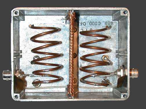
Construction detailsThe unit was constructed in a diecast box, approximately 120mm wide, 90mm high and 55mm deep. I used a commercial aluminium alloy diecast box, but zinc alloy ones are also available. The box was divided into two compartments, each approximately 57mm wide, 85mm high, and 53mm deep, by a central aluminium screen approximately 1mm thick which was made to fit into slots on either side of the box. If your box has no slots, simply make a screen to fit the box. To earth the central screen to the box lid and sides, the screen was made a loose fit, but packed tight with braid from coaxial cable, RG58 braid at the sides where the screen meets the box and RG213 braid where the screen meets the box lid. You can see the lid braid clearly on the picture below. The lid braid was lightly soldered to the edge braid to make a more stable assembly. The base side of the dividing screen was attached with three screws, but you can use more if you want! The central screen is solid; there is no gap apart from the 1mm or so hole through which L3 passes.� In fact, you could route L3 outside the box, if you prefer.� In my own case, my imprecise metal working allowed a small triangular gap between the corner of the screen and the junction of the box base and side.� There was just enough gap to pass the cable through. The two helical resonators were made from 2.5mm diameter solid copper wire, the largest I had to hand. I am trying to obtain thicker, more stable wire, and the brake fluid pipe from cars is a possible source. I found that both 3.2mm and 4.6mm copper pipe was available, but I have not tested this in an RF application myself. To attach the resonators to the aluminium box, I used two large screws and soldered the copper wire to the screws. It is important that the resonators be mechanically stable as the filter should have a stable notch frequency. The two JFD 1-14pF piston tuning capacitors were mounted in the base of the box and look like brass nuts in the photo below - they are actually gold-plated. The trimmers are attached to the resonators at two turns, and the coupling capacitors at about 3/4 of a turn. BNC connectors were used, attached to the walls of the diecast box. To attach the coaxial cable outer to the connectors, I made up small brass plates which can be seen as dark "flaps" just below the BNC connectors. I expect copper would be better than brass, but none was to hand. The cable linking the input and output connectors is dressed as near to the edges of the box as possible, and passes through a small gap left at the lower edge of the dividing screen between the screen and the box edge. Use as small a gap as possible to allow the cable to pass.
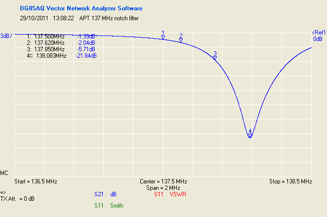
AlignmentWith the filter completely assembled, and the box lid firmly attached. adjust the two tuning capacitors for resonance at 138.45MHz (suggested). There will be slight interaction between the two trimmers, but not a lot. The resonant dip is very sharp! A frequency-accurate signal generator is required. PerformanceI don't have super-accurate measurement kit, so I'd love to hear from someone who makes more accurate measurements on this type of filter.
Several years later, after continuous operation, I was eventually able to measure the response. The filter was not re-aligned before the measurements below were made.
Suggestions for further experiments
PostscriptYou will note that I am neither an expert constructor, nor a particularly good metal worker. The entire filter was made from items in my scrap box. I am presenting these details here in the hope that someone with better facilities than I have might develop this filter and perhaps come up with some modelling parameters so that design can be optimised. I intend to try and develop simulation models to gain a better theoretical understanding of the filter, but I don't know if I have the software or expertise for this. Using this filter to remove 144MHz (2m) Amateur Radio transmissionsThe requirement in this application is for a greater notch depth, but at a slightly greater frequency separation. Karl-Heinz Gansel (DL6EBS) writes [with minor DJT edits]: Hello David, I built the filter in a smaller box with different L and C.
C3 is 22pf and C4 is 8.2pf and I get a 4.5db loss in 137Mhz, but about 42db suppression
at 144.7 MHz. Now I have no problems with my neighbour, even when he
transmits with 50 Watts :) I think 4.5db loss is no problem [in this
application], because the Notch Filter is behind the preamplifier which provides
about 20dB gain. Later he wrote: Here the newest frequency response trace. I have recalibrated the two helical
notch filter and get now 4 db loss and 47db suppression.
| |||||||||||||||||||||
|
|