|
| |
GPS 18x LVC interfacing to a Raspberry Pi
Some notes from Pete Stephenson.
Introduction
Pete writes: I recently acquired a new oscilloscope (a Rigol DS1054Z, if you're curious) and wanted to do some testing of the GPS 18x LVC that I have
connected to my Raspberry Pi. I thought you might be interested in some of the results.
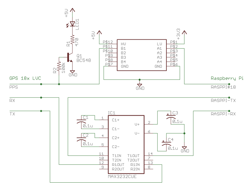
I have the GPS connected to a DB9 serial connector with a hood. The PPS line is connected to a 100k ohm resistor that drives the base of a
BC548 transistor in order to blink an LED. It is additionally connected, by means of some DB9 breakout boards and jumper wires, to a
level shifter [1] to convert between the 5V PPS signal the GPS emits
and the 3.3V input required of the Pi . The serial Tx/Rx lines are connected to a RS232-to-TTL serial converter board that uses a MAX3232
chip [2].
That said, I should have used a MOSFET or a buffer IC instead of the BJT transistor I
used; the BJT sinks a tiny amount of current from the PPS line, while a MOSFET or buffer wouldn't.
Alas, one is limited to the parts on hand. That said, if one still wishes to use a BJT, one can use pretty much any
NPN transistor. I just happened to have a bunch of BC548s in the parts drawer.
I'm afraid I didn't have an Eagle part model for the MAX3232 board I received (which already has the DB9 connector, capacitors, etc.), so I
showed the circuit using a bare MAX3232 chip - datasheet.
If one is going to use the bare chip and is using polarized capacitors, be aware that pin 6 involves a negative voltage so be sure C4 is
properly oriented (e.g. with the (-) side of the cap connected to pin 6 and the (+) side of the cap connected to ground).
If one uses non-polarized capacitors (a much better idea), it doesn't matter.
0.1 µF multilayer ceramic caps work great and aren't polarized.
The model in Eagle didn't have pins for Vcc and Gnd for the chip, but they should be connected to the Raspberry Pi's 3.3V and Gnd connections,
respectively. The RS-232-polarity signal from the GPS is connected to pin #13 ("R1IN",
think "RS232-line-1-in"). The corresponding TTL output signal is available from T1OUT ("TTL-line-1-out") and is connected to the Pi's Rx pin.
The Pi's Tx pin is connected to T1IN. The converted RS232 signal is available on R1OUT, which is connected to the GPS' RX line.
MAX3232 Board Details
If one uses the board, things are much easier. The Vcc pin on the board is connected to the Pi's 3.3V supply, Gnd is
connected to the Pi's ground, Rx on the board is connected to Rx on the Pi, while Tx on the board is connected to Rx on the Pi.
DB9 Wiring
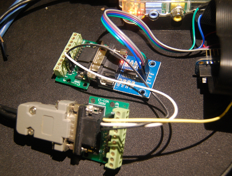
I've also included an image that shows the setup. The GPS is connected to the
grey DB9 hood on the bottom-left, and includes a pigtail going to a USB port for 5V and
GND. Pin 1 (yellow) goes to the level-shifter, which is not shown in the image.
Pin 2 (white) carries the data transmitted from the GPS and is connected to pin 3 of the top breakout board.
Pin 3 (black) carries data
transmitted from the Pi to the GPS, and is connected to pin 2 of the top breakout board.
Why the pin-swapping? Recall http://www.db9-pinout.com/ -- male and female connectors have reversed pin
numbering - a female transmits on pin 2 while a male receives on pin 2, and a female receives on pin 3 while a
male receives on pin 3. Both the DB9 hood and MAX3232 board are female, while both DB9 breakout boards are male, so the Tx/Rx pins need to be
swapped between the breakout boards.
The top breakout board is connected to the MAX3232 board, which is connected to the Pi.
As this is just a prototype, I'm using the breakout boards. Things would be a lot neater if done on a PCB.
Some interesting results
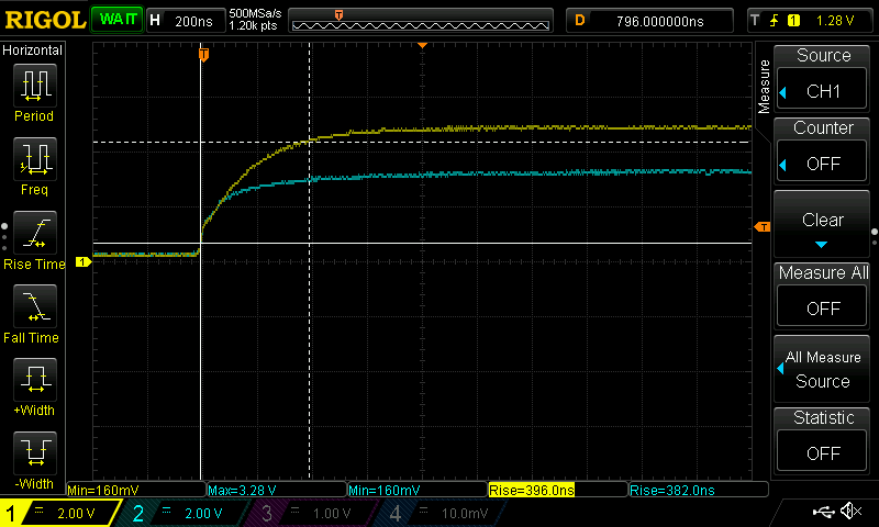
- If the DB9 connector is unplugged, the 5V PPS rise time is ~350ns. If the DB9 connector is connected to the level shifter, the 5V PPS
rise time increases to ~370ns, still well within the 1µs tolerance specified by Garmin.
I have not tested the rise time of the unloaded PPS line; all my measurements are with the LED-driving transistor
connected to the PPS line (indeed, I can't remove it even if I wanted; it's all inside the DB9 hood which has been potted with epoxy).
In normal use the rise times vary by a few nanoseconds from pulse to pulse.
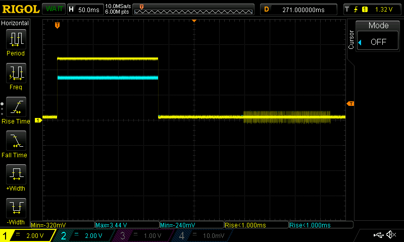
- There is no detectable delay using the level shifter.
The yellow line is the 5V PPS signal from the GPS, the blue line is the 3.3V level-shifted PPS
signal from the MAX3232.
Even with the oscilloscope
dialled as far down as it goes (5ns/div) the two lines overlap and there's no
measurable delay. This pleasantly surprises me.
- There is detectable (~0.9 V peak-to-peak) cross-talk between the PPS and GPS's serial Tx line.
First looking at the PPS signal:
As above, the yellow is the GPS output and blue the MAX3232 output.
Below shows more detail of the noise during the off period:
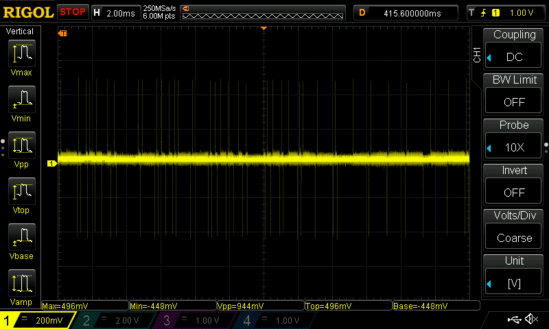
Fortunately this noise is well below the +/- 3V "on" threshold for RS-232 receivers, and so there's no spurious
triggering of the PPS line by the cross-talk.
- The MX3232 is incredibly useful - it's capable of taking RS-232 (-Vcc to
+Vcc) polarity and voltage data and converting it to TTL-polarity (0 to Vcc)
signals [3].
The more common MAX232 can only do 5V to RS-232, while the 3232 can go down to 3V.
The Pi's UART uses TTL-level 3.3V signals, so having a converter chip is a must.
Decoding the bytes
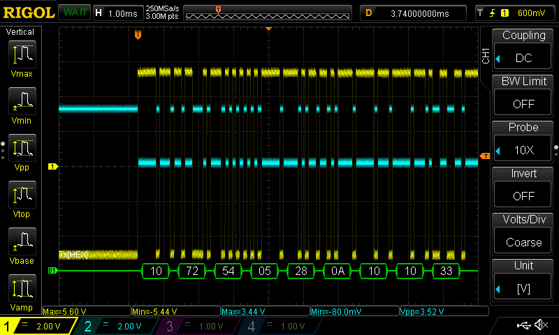
You can clearly see the GPS and MAX3232 in operation in the screen-shot
above. The GPS is the blue channel and the MAX3232
output is the yellow channel. The scope has helpfully decoded the first few bytes of the Garmin binary protocol (bonus points if you
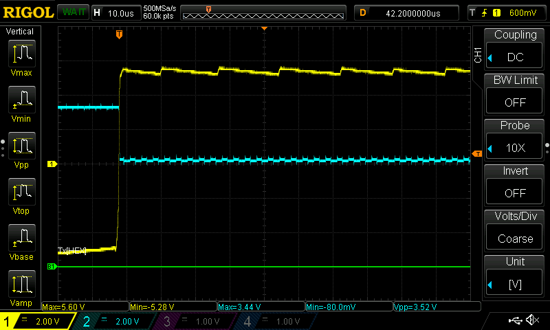
identify which sentence is being sent). The "fuzzy" edges are due to the charge pumps in the GPS and MAX3232 maintaining the needed voltage
levels; see the close-up below.
|