


|
|
Timekeeping with the Sure GPS evaluation boardAlthough this page is about using a particular board to provide GPS and PPS information over a 9-pin RS-232 connector, I've also used other boards intended for small PCs such as the Arduino, BeagleBone and Raspberry Pi - the Adafruit Ultimate GPS Breakout - 66 channel board is such a device. These typically have a 3.3V signal output which may not be enough to drive a typical serial port, as that level doesn't meet the RS-232 specification. In that case you can use a level converter such as https://www.amazon.co.uk/gp/product/B00EJ9NAKA and power it off the same 5V source as the GPS - perhaps from a USB port using just the ground and +5V leads. The basic steps are:
Using the Sure boardSome experiments using the Sure Electronics GPS evaluation board for NTP. If this board appears not to be available:
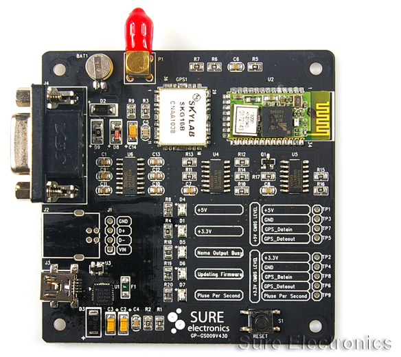
I was alerted to this board by the TimeNuts list, and inspired by Tom Van Baak's Web page. The unit is not just the board, but comes with a GPS magnetic mount antenna puck, and a USB cable, so it's a ready-to-go GPS unit.
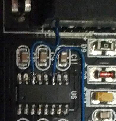
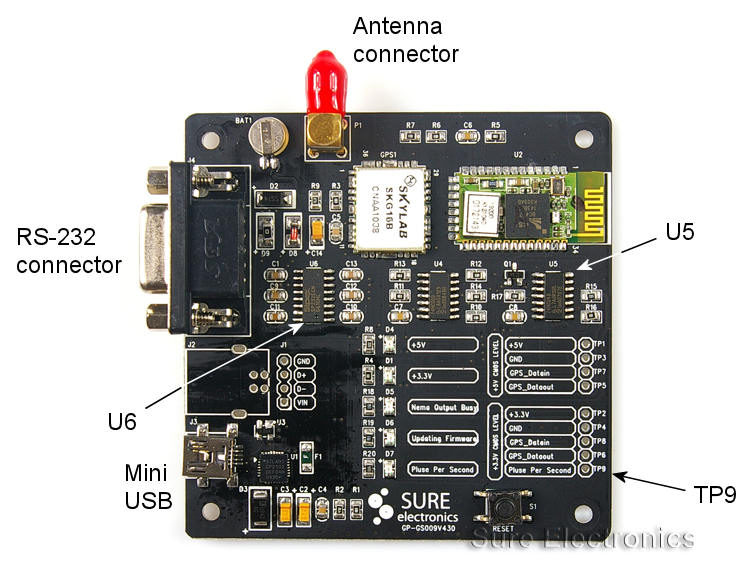
Meeting the PPS over RS-232 requirementThe purpose of the patches is to provide a true RS-232 level PPS signal on pin 1 (DCD line) of the connector. Whilst the PPS signal on test point TP9 could be used, it is at CMOS level and not RS-232 level, and may not be recognised correctly by the RS-232 receiver chip in your PC. You can try it if you like, of course. I have provided a Serial Port LEDs program to show the status of the RS-232 control lines. Fortunately, there is an unused CMOS-to-RS-232 level converter gate available in U6, with its input on pin 11 and its output on pin 14. However, as this is an inverting gate, and we want a positive going PPS signal, it should be driven with a negative going PPS signal. That available at TP9 is positive going, however it is also used to drive the ridiculously bright blue LED through a CMOS inverter gate in U5, so by taking the output from that inverter on pin 8 of U5 we have the required negative-going PPS signal to drive U6. .. or as a picture
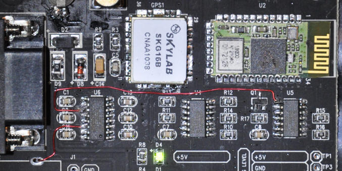
The two red patch wires shown below were added by me to provide an RS-232 level, positive-going PPS output. Note that with the Windows NTP port, the DCD line must be asserted (positive going) as provided by this patch, as that port cannot use an inverted DCD signal. Krysztof Zaraska notes:
Board patchesOnly two wires need to be soldered to make the required patches - one is just on the top of the board, and the other goes through the hole near the RS-232 connector to connect to points on both the top and bottom of the board. I used solid enamelled copper wire with the enamel removed at the ends for soldering. Of course, patching the board like this invalidates the guarantee.
You can check that the patch is working with my Serial Port LEDs program, which shows the status of the RS-232 control lines. Watch for a brief white flash of the DCD indicator once a second which should approximately coincide with the timing of the brief bright blue flash of the Sure board LED. Easier alternativeOne person has reported that he has obtained satisfactory results connecting
the TTL-level positive-going signal on TP9 directly to pin 1 (DCD) of the RS-232
connector. This may be easier if your soldering abilities are not as good
as you wish, as the connection points are larger and easier to solder to. This does work with the serial ports on many PCs, but may
result in a lower protection against electrical noise if you have a long lead
from the Sure board to your PC. A couple of metres lead length should be
fine for this method, but possibly not an 80 metre run near interference sources
such as electrical machinery - i.e. anything with power switches or
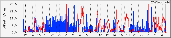
motors. Try it and see, but use at your own risk. The Sure evaluation board in use - it works well!Initial tests were with a Windows 2000 system (PC Bacchus) running ntpd 4.2.7p97-o, from Dave Hart's site (you may need a 64-bit version, for example) and the board worked perfectly once the NTP serial rate was changed from the NTP default of 4800 baud to the board default of 9600 baud. If you are running a different version of NTP, you may find that it doesn't pick up the GPS properly, and the reach will stay at zero. To ensure that NTP does not select the wrong second (by interpreting one of the trailing NMEA sentences as near the second marker), you should also set bit 1 (decimal 2) of the mode parameter. Here is what I used: # ref-clock drivers server 127.127.20.1 minpoll 4 mode 18 prefer # NMEA serial port, 16 = 9600 baud, 2 = $GPGGA server 127.127.22.1 minpoll 4 # PPS - serialpps.sys - on COM1: I only realised the importance of selecting the $GPGGA sentence after earlier testing with the same NTP version, where on a Dell PC running Windows XP (PC Feenix) where it seemed as if the NMEA was sometimes picking up on the wrong second, or at least showing a substantial offset. Similar issues have been seen with later firmware on the Garmin GPS 18x LVC. It appears that some NTP versions may make use of use the last sentence received, rather than the first sentence - and the logic for doing that currently escapes me! I reported a bug and that has now been fixed. As the Sure unit sends several sentences, there is a chance that the final sentence will be nearer to the following PPS than to the leading PPS edge. [On reflection, as the $GPGGA sentence carries no date information, it would be unsuitable for a stand-alone system. The $GPRMC sentence would be more appropriate.] In an early test, using a higher baud rate and $GPGGA selection, the NTP jitter seen on the Windows-7 PC was the same whether the Garmin GPS 18 puck or the Sure-GPS board was used. The same was true on the Windows 2000 PC, even with the default 9600 baud rate and default NTP configuration. No tests have been made to compare the PPS signal on a more precise level, but on the basis of present tests I believe it is within 10-20 microseconds, and likely within a microsecond or better. I'd love to hear of any more exact measurements. I'm currently using two of these Sure Electronics boards with the magnetic antenna puck indoors (on the top floor of a two storey building) with two Windows-10 64-bit system. Windows-10 64-bit systems show an averaged jitter of about 40 microseconds. I use Meinberg's loopback-ppsapi-provider.dll. I've written up the Windows-10 system - it is of particular interest as normally you are not allowed to use unsigned drivers on such a system. Here is the current live data, where the offset reported by NTP is plotted against time of day. Click on a graph to see the weekly, monthly and yearly data.
The difference between the smoother, slower-changing but greater offset in the XP system and the smaller but more rapidly changing offset in the Windows-7 system is typical, and may be due to the difference between the software clock rates. I would expect a system using FreeBSD to perform even better. Success has been reported with FreeBSD by Adrian Urquhart, also using 9600 baud from the Sure board. .. but an anomalous output (now resolved)Although two of these boards have been working well here for some time, I recently had cause to use an NTPQ command to check the GPS sentences being sent by these units. While the sentences were ok, the ntpq -c "cv &2" command revealed that the serial data was not as continuous as expected, and may have contained some errors. For four PCs here:
Strange that only those connected to a Sure board produced the non-zero
noreply and badformat counts. The jitter reported was quite normal, so it
seems that any errors in the serial data aren't a problem, providing that the
PPS line stays good. Both of the puck antennas for the Sure boards and the
GPS 18x puck were located indoors, with the GPS 18 being on the roof. Update:
In February 2012 this was reported as bug
2140, and the bug was fixed in NTP 4.2.7p258 and later. This
site has the binaries for various NTP versions, including 4.2.7.p258. Testing the board functionBefore making any changes to the board, you may want to test its function. For other boards you should ensure that you are seeing a valid NMEA output from the serial port, and that the DCD line is waggling using my Serial Port LEDs program. Suitable software for the Sure board can be downloaded here: http://www.sure-electronics.net/download/index.php?name=GP-GS010&type=0 I suggest you get:
First set up the board with USB power (no need for a data connection) and antenna. Leave it for several minutes until the blue LED starts flashing. The LED sequence is blue (short flash), yellow (longer flash), just the greens (about the same time as the yellow). This could take 15 minutes on the first run when the whole satellite almanac may need to be downloaded. Next: find a free serial port on your PC (mine was a USB to serial adapter on COM4), and connect the device to that port with a serial cable. I used this 9P male to 9S female lead from Amazon: http://www.amazon.co.uk/gp/product/B001R092VK/ref=oss_product.
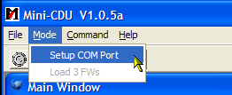
Checking the board is workingStarting with download MStar MiniCDU.zip, unzip the file to a convenient location such as C:\Tools\Sure\, and double-click on MiniCDU_V1.0.5a.exe. These screen-shots are from a Windows XP SP3 system. Use the Mode, Setup COM port menu to match your PC's COM port, and be sure to set the speed to 9600 baud as that is what the unit uses out-of-the-box. Cursor gone wild?It's possible that Windows will detect the GPS as a serial BallPoint mouse and send the cursor dashing all over the screen in an out-of-control manner! Should this happen (and in my experience it's more likely than not), see the fixes here or here. I found that disabling the affected device was the best way.
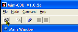
Click on OK to save the COM port settings. You should now be able to click on the connect icon, the first in the toolbar at the top:
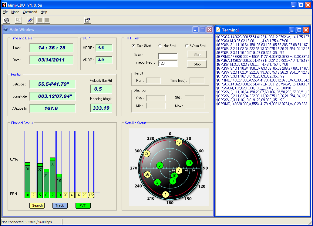
The terminal window should start to fill with groups of NMEA sentences in one second batches, starting with $GPGGA and finishing with $GPRMC. You should get location details and satellite signal levels recorded as well. The very eagle-eyed amongst you will spot a formatting error in the displayed position!
| ||||||||||||||||||||||||||||||||||||||||
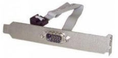
No COM port on the back of your PC? Not to worry! Many PCs have COM port support built into the
motherboard, but the 9- or 10-pin header is not wired to a 9-pin male
connector on the back. You may be able to cannibalise an old PC for a suitable
back-plate and header, or get one from Amazon - search on "9-pin serial header".
Choose the right size for your PC's backplane - for example: |
 |
If all you have is a serial port over USB that's better than nothing providing the port emulation includes the DCD line (pin 1 of the 9-pin RS-232 connector). As the serial-over-USB built into the Sure board may not include emulation of the DCD line with the pulse-per-second signal, it is unlikely to be anything like as accurate, and I do not recommend you to use it.
Update: Richard Steedman notes that using the drivers from the SiLabs Web site the DCD signal is carried over USB when using the modifications below.
# Use drift file
driftfile "C:\Tools\NTP\etc\ntp.drift"

# ref-clock drivers - Sure Electronics GPS board
server 127.127.20.1 minpoll 4 mode 18 prefer # NMEA serial port, 16 = 9600 baud, 2 = $GPGGA
server 127.127.22.1 minpoll 4 # PPS - serialpps.sys

# Use UK pool NTP servers as a backup
pool uk.pool.ntp.org minpoll 7 maxpoll 7
As mentioned above, you will want to play with using the loopback-ppsapi-provider DLL for better performance on this reference PC, as well as trying NTPD_USE_INTERP_DANGEROUS=1 on Windows Vista or Windows-7 systems, but you will not need to alter the configuration file to test these options. Windows-8 and later includes a more accurate time API allowing better performance - you don't need the ..INTERP.. fix. Note that the pool directive requires NTP later than 4.2.6 (IIRC). Change the prefix (UK) to suit your region - there is a list of both continental and country regions here.
Note that you must mark one of you other servers with the "prefer" tag, otherwise the PPS driver won't know where to get the current time from (to the nearest second). You can have more than one server marked with "prefer".
The aim here is to make the LAN- or wireless-connected PC talk to the stratum-1 server more frequently than normal, so that it has a better timekeeping performance. This achieved with the maxpoll 5 option, which forces polls to be at 32 seconds intervals maximum (32 = 2^^5). To make sure that the Internet backup servers are contacted no more frequently that is absolutely necessary, they are set to 1024 second interval (1024 = 2^^10). Suppose your reference PC, your local stratum-1 server, is on 192.168.0.3:
# Use drift file
driftfile "C:\Tools\NTP\etc\ntp.drift"

# Use local stratum-1 NTP server - you will need to alter this address
server 192.168.0.3 iburst maxpoll 6 prefer

# Use pool NTP servers as a backup
pool uk.pool.ntp.org minpoll 6 maxpoll 6
Have fun, and do report back on how you get on!
While not required for NTP use - where the default 9600 baud works correctly provided you tell NTP to use the first sentence ($GPGGA) - here is how you could set the baud rate for some other application. Please note that at least one person (Terje Mathisen) has reported that the board loses it programming after several hours without power, so I suggest you work with the default settings if possible.
Expand the contents of the zip file GPS.zip, perhaps into the same directory you used before. Note that there several files including GPS.exe and help.html, and three sub-directories. Double-click on help.html to read how to change the baud rate from 9600 baud.
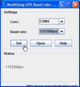
Double-click on GPS.exe, and you will get a dialog where you can set the initial port and baud rate.
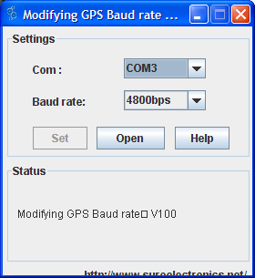
For my PC, as mentioned above, the port is COM4, and the initial baud rate is the default of 9600, so I have two settings to alter. Once the settings are changed, press the Open button. You should see the program searching at the various baud rates and COM ports. Mine settled on 9600bps after a couple of seconds:
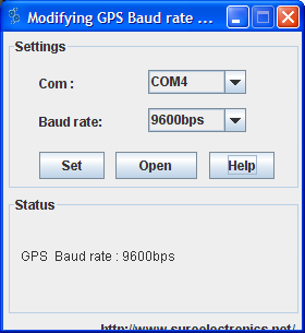
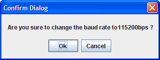
If you have problems with this software not recognising your GPS, it may be that you need to update your Java to a more recent version (thanks to Adam Feigin for that). Now you can set the baud rate to the new value (115,200) and press the Set button:
At the confirmation dialog, press OK:
and you should see a success message:
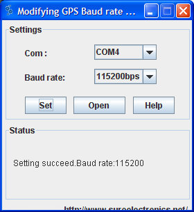
You can check that the rate has changed by re-running the MiniCDU_V1.0.5a.exe
program, and setting the 115,200 baud rate there before pressing the Connect
button.
Róbert Árkosi wrote with the following tip:
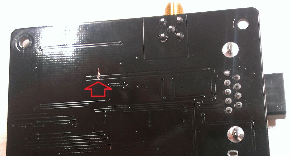
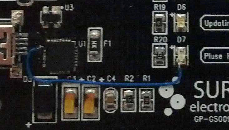
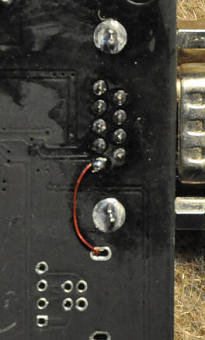
Here's my tip for Sure GPS Evaluation board owners. If they want to disable the on-board Bluetooth module, for security reasons and avoiding RF pollution, all they have to do is to cut the power line that goes to the module.
See the picture below. On the back of the board, cut by scratching the track marked with the red arrow using a sharp tool like a knife or a small screwdriver. That will simply disable the Bluetooth module by hardware, not giving it power. Can be restored by soldering.
You wrote that it's already inoperative on the new board, that was not my case. It seems that the Bluetooth module starts working only after the receiver has a GPS fix, it can be found on the air by the name "Sure".
Done the mod with two receivers, all working fine. Please feel free to add this info to your great article, so others can use it too.
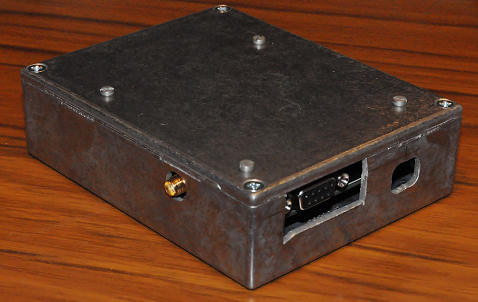
[DJT: I've not found this to be a problem with my two Sure boards, but one is
in a screened metal box, and they are both from early 2011, so perhaps the design
has changed slightly.]
Adrian kindly sent notes on his experience from using the Sure board.
Easier connection to the serial DCD pin. |
|
 |
I wired up the PPS to pin 1 of the serial port as per your method, except I used plastic insulated wrapping wire rather than enamelled and I stuck the wire through the board using the same hole as the serial port pin uses (there's easily enough room, just melt the solder). |
|
 |
Frits W1FVB reports: When I connected pin 1 from U1 to the negative side of D7 (very very bright LED), my Windows computer didn't recognize the GPS Board anymore. Perhaps the virtual com port driver in Windows can't handle the DCD signal? |
Richard Steedman reports: I can report that I am getting the PPS to display correctly on your
Serial LEDs display program with both the Virtual COM port drivers from the Sure website (v5.0) and the latest drivers from SiLabs's website (v6.7).
So I haven't seen Frits W1FVB's observed behaviour. |
More and more PCs these days are not fitted with COM ports, nor are there port headers on the motherboard to add a port yourself. However, a recently purchased PC had neither of these options, but I thought, no problem, I can get an add-in PCIe board. However, I found that Dave Hart's serialpps.sys driver didn't function with the board, as it used its own version of serial.sys. I thought that this meant I could not have PPS active on that computer, so I was using it with just LAN network sync until recently, when I discovered a hidden gem called the loopback PPS DLL, developed by Meinberg. What this driver does is to detect the DCD edge on pin 1 of the RS-232 connector and use it as the precise timing for the start of the second, but in contrast to Dave Hart's serialpps.sys, which detects the DCD edge at device driver level in kernel mode, the loopback-pps software detects the DCD edge in user-mode, meaning that it doesn't require a special device driver, and that, in principle, it will work with "any" serial device ("any" being the one device I've tested, at least!). The hardware steps are identical to those described above - to present at least a three-wire connection to the PC with the TX data from the Sure board, the DCD line, and ground. In fact, I made up a special cable which paralleled the output data from the Sure board to two female 9-pin connectors, connecting the RX input to the Sure board to just one connector.
Only one new file is needed, the DLL itself which NTP will call if configured. The file is loopback-ppsapi-provider.dll which may be included with the Meinberg installation, or if not you can get it from my own builds (made with Visual Studio 2015). My own builds are here. Copy the file: loopback-ppsapi-provider.dll to the same directory where ntpd.exe lives. Note that my DLL is a 32-bit one. You should choose the DLL to have the same bit-size as the ntpd.exe you have installed. I use 32-bit for both, even on a 64-bit system. You can use any directory, but it's neater if you keep all the NTP executable files together. Remember to right-click, Properties, Unblock the Zip archive before extracting the file after you download the Zip over the Internet. The next step is configure NTP to search for the PPS support file, and add the required lines to your ntp.conf.
You need to tell NTP that support for PPS exists, and this is done by setting a system environment variable to point to the location of the DLL you have just copied. How to edit environment variables describes the process for Windows-8 and -10. You need to set the system variable as follows:
Name of variable: PPSAPI_DLLS
Value: <path-to-the-dll>
for example:
Name of variable: PPSAPI_DLLS
Value: C:\Tools\NTP\bin\loopback-ppsapi-provider.dll
The new variable will only be seen when you restart NTP. Be sure to create a new System variable, and not a User one! From NTP 4.2.8p10 onwards, it's preferred that you use a registry setting rather than an environment variable - see here. A typical setting might be:
Key: HKEY_LOCAL_MACHINE\SYSTEM\CurrentControlSet\Services\NTP
New: Multi-String Value named PPSProviders
Value: loopback-ppsapi-provider.dll
NTP 4.2.8p10 may have a bug requiring the environment variable to have a dummy trailing part if the full path isn't given:
Name of variable: PPSAPI_DLLS
Value: loopback-ppsapi-provider.dll;dummy
Krzysztof Zaraska has provided a registry settings file which enables loading of the loopback-ppsapi-provider.dll and serialpps-ppsapi-provider.dll, disables the serial mouse driver, and sets NTPD to use the NTPD_USE_INTERP_DANGEROUS environment variable (only recommended for Win-7 and earlier). Use which parts you need:
Windows Registry Editor Version 5.00 [HKEY_LOCAL_MACHINE\SYSTEM\CurrentControlSet\Services\sermouse] "Start"=dword:00000004 [HKEY_LOCAL_MACHINE\SYSTEM\CurrentControlSet\Services\NTP] "PPSProviders"=hex(7):6c,00,6f,00,6f,00,70,00,62,00,61,00,63,00,6b,00,2d,00,70,\ 00,70,00,73,00,61,00,70,00,69,00,2d,00,70,00,72,00,6f,00,76,00,69,00,64,00,\ 65,00,72,00,2e,00,64,00,6c,00,6c,00,00,00,73,00,65,00,72,00,69,00,61,00,6c,\ 00,70,00,70,00,73,00,2d,00,70,00,70,00,73,00,61,00,70,00,69,00,2d,00,70,00,\ 72,00,6f,00,76,00,69,00,64,00,65,00,72,00,2e,00,64,00,6c,00,6c,00,00,00,00,\ 00 [HKEY_LOCAL_MACHINE\SYSTEM\CurrentControlSet\Control\Session Manager\Environment] "NTPD_USE_INTERP_DANGEROUS"="1" |
Note that if you use the registry file you won't need to set the PPSAPI_DLLS environment variable.
Perhaps if you are reading this section you already have NTP working, but just off Internet or LAN servers, so you need to add the lines which tell NTP about both the COMport which has the NMEA sentences from the GPS, and also DCD PPS signal which you want to use for precise edge-of-second. Here's an example where my COM port driver is on port COM3. You can use the Device Manager to check which port you system uses if you are unsure. I added the lines below to my ntp.conf:
server 127.127.20.3 minpoll 4 maxpoll 4 mode 16
fudge 127.127.20.3 refid NMEA

server 127.127.22.3 minpoll 4 maxpoll 4
fudge 127.127.22.3 refid PPS
The first two lines are for the type 20 generic NMEA/GPS driver, and "mode 16" sets the port to 9600 baud, as described here. 9600 baud matches the default Sure board setting. "3" is the port number, COM3 in my case. If you wish to operate without any Internet or LAN servers you will likely need to add a fudge factor to the type 20 server to best align its output with the second edge. The time offset will be subtracted from the measured arrival time of the serial data to make it appear as if it were on the second. You will also need to mark the serial source as "prefer". For the Sure board I have, I needed:
server 127.127.20.3 minpoll 4 maxpoll 4 mode 16  prefer
fudge 127.127.20.3 time2 +0.400 refid NMEA
If you are using LAN servers, mark one or more of them "prefer", for example:
server 192.168.0.20 minpoll 5 maxpoll 5 iburst prefer
The second two lines are for the type 22 ATOM/PPS driver, with "3" again being the COM port number.
My own preference is for the output of an ntpq pn command to list the most precise server first:
o127.127.22.1 .kPPS. 0 l  6 16 377 0.000   0.025 0.008
x127.127.20.1 .NMEA. 0 l  5 16 377 0.000 -24.887 9.770
*192.168.0.20 .GPS.  1 u 12 32 377 0.169   0.053 0.046
so I changed the order of the lines in the ntp.conf file to be:
server 127.127.20.3 minpoll 4 maxpoll 4 mode 16
server 127.127.22.3 minpoll 4 maxpoll 4
but when I did this, NTP stopped working and would not response to a Stop Service command. It seems that there might have been a bug which required the serial driver to be listed before the ATOM driver, at least when using the loopback-pps function. Perhaps it has been fixed by the time you read this. The output from my system now displays as:
x127.127.20.3 .NMEA. 0 l 15 16 377 0.000  -474.10 4.906
o127.127.22.3 .uPPS. 0 l 14 16 377 0.000    0.015 0.002
*192.168.0.20 .GPS.  1 u 12 32 377 0.139    0.074 0.052
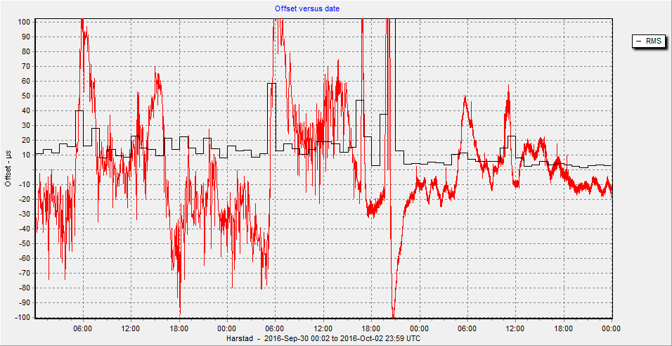
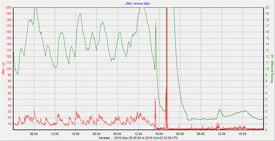
Below are graphs showing the reduction in offset and jitter recorded in the loopstats statistics recorded over a three day period with the changeover on the middle day. Click on a graph for a larger image. The offset is now less variable, transients of 100 µs have been reduced to some 50 µs, and the averaged jitter has been reduced from 15 µs to 2.5 µs. This particular PC Harstad has a light CPU load but regular network I/O on two adapters (around 7.5 Mbps in on one adapter and 5.5 Mbps out on another, with a real-time reception processing software in between).
|
|
|
Hal Murray notes:
I'm in the habit of using things like: cat /dev/ttyUSB0
when checking out GPS that I expect to send ASCII. When I tried that with my new toy, it went bonkers.
In particular, the firmware LED went on, and the NMEA LED switched from blinking to solid on.
The data included the stuff I expected, but it also included a lot of garbage.
I (finally) tracked that down to "echo" being set on the tty parameters. That
echoes a copy of each input character back to where it came from. The cure is as simple as:
stty -F /dev/ttyUSB0 -echo
Of course, there are other ways to get in trouble with tty parameters. Here
is the line I have stashed away in my notes on how to set things up: stty -F /dev/ttyxxx 9600 igncr clocal -echo -ixon
Now that I've got that sorted out, it responds to the $PTMKxxx commands. (I've only tried one.)
The Sure card uses the ST CP2102 USB to serial chip. It's not very common,
but there is a Linux driver for it. I assume the default bits somewhere in
the driver are different from defaults in the FTDI FT23x and the Prolific PL230x chips that are quite common.
I haven't looked at the source code.
In my quest for a low cost, no-soldering GPS gizmo that works well with NTP, I tried a
Transystem
GM-2. It had the same sort of garbage. That was a while ago. I gave up and put it on the back burner.
Guess what? It uses the same USB-serial chip. It's working now.
Don Latham responded:
The CP2102 is featured in Chinese eBay 4 buck usb-232 adapters. The chip suffers from serious bad-driveritis, and I've had to do 'net research to make it useful with various flavours of Windows.
(From a posting on the Time
Nuts mailing list).
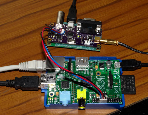
J Beale has used this board to make a Raspberry Pi computer into a stratum-1 NTP server with sub-100 microsecond offset. More information here:
http://www.raspberrypi.org/phpBB3/viewtopic.php?f=41&t=1970&start=25#p142606
My own Raspberry Pi NTP notes are here.
|
|

