


|
|
The Raspberry Pi as a Stratum-1 NTP ServerAs an experiment, I purchased one of the low-cost credit-card-size Raspberry Pi computers, and have configured it to run NTP (Network Time Protocol). I have also used this board with a GPS receiver with pulse per second (PPS) output to make a stratum-1 NTP server, but as I know little of Linux, it has taken some time to achieve this aim! There are some helpful Linux commands scattered throughout this page. These notes are almost as much for my own records for the next time I need to visit this project, but I hope they may be helpful to others. If you want to get started quickly, with the best results for minimum fuss, please see my Raspberry Pi NTP quick-starter page. Please also see that page for issues with the Jessie release of Linux, and with the newer Raspberry Pi model 3. I start by describing how to get the Raspberry Pi running with just a LAN connection - no display, keyboard or mouse - a so-called headless operation. I then describe how to configure NTP for your environment, and adding a GPS/PPS receiver to convert your box into a stratum-1 NTP server including the operating system updates needed. Next, I note a couple of problems I had with the first GPS receiver I tried, and how I cured those with a different GPS receiver to produce a stratum-1 NTP server consuming about 4 watts. The easiest approach with good performance is described here. Since starting this page there have been two developments which make the process somewhat easier - a program has been developed which allows the use of an unmodified operating system by working in user-mode rather than kernel-mode PPS, and a module is now available which plugs directly onto the 26-pin GPIO header of the Raspberry Pi, so no soldering is involved. My thanks to Folkert van Heusden and Anthony Stirk for these developments.
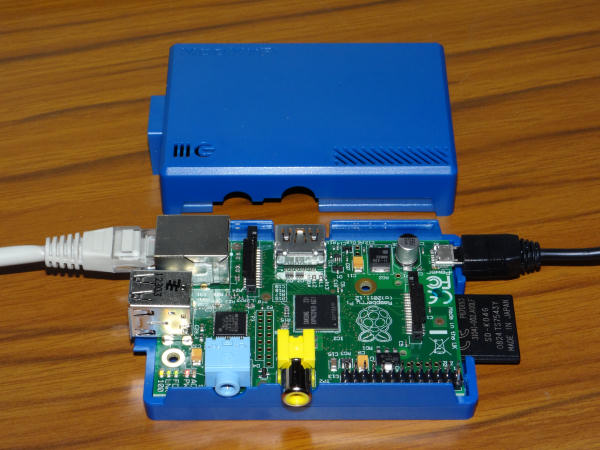
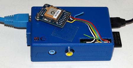
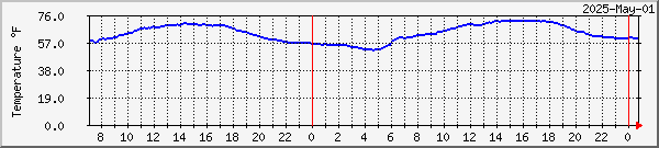
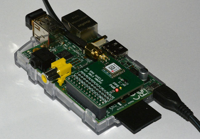
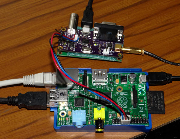
Note that the Adafruit GPS Hat uses GPIO 4, physical pin 7, so you would need to change the commands given in this document. Later additions have included remote monitoring of the NTP server performance, and more general monitoring of the Raspberry Pi using the standard SNMP functions, with an additional CPU temperature monitoring add-on. My main Raspberry Pi page may also be of interest. Note that good performance is dependant on the GPS unit having a clear view of the sky, particularly the southern part of the sky if you are in the northern hemisphere. With older GPS receivers this required an outdoor antenna, but more modern units such as those mentioned here may well work indoors providing that some sky is visible, perhaps on the top floor of the building (as I am). If you have an "RF-proof" roof (lead-lined, perhaps?!) or certain windows with a lining to stop incoming heat, or wall construction including metal, you may still need an outdoor antenna, and almost certainly if you live in a basement! Whilst weather will normally have only a small effect in the signal - e.g. heavy rain - it's possible that a layer of snow could attenuate the signal enough to stop the GPS receiving enough signal. Monitoring performance may help you spot these problems. (Thanks to Joe, HB9DRT for the information on snow - I've only seen that problem once here during an exceptionally cold winter). If changes in ambient temperature are reducing the precision you expected, look at ntp-heat. IntroductionThe Raspberry Pi is a credit-card size computer, available from distributors across the world. I bought an attractive blue case and 5 V, 2 A power-supply from ModMyPi. You can see the Ethernet lead on the left, and the 4 GB SD card with the operating system on the right, together with the micro-USB power lead. There is a model-B (shown and used below), and a lower-spec model-A which may become available at some time in the future. I'm using the 512 MB model-B, introduced in Autumn 2012.
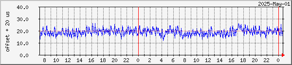
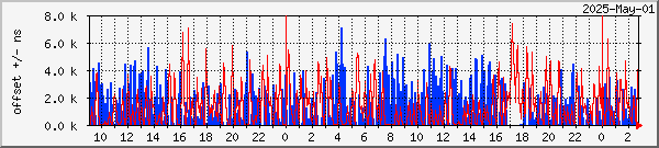
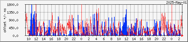
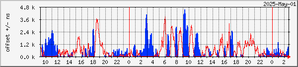
What results can I expect?Shown below are the offset results with the Raspberry Pi in three configurations: with WAN-only connections syncing to the Internet (as you might find it a typical home situation), with LAN connections to a local stratum-1 server, and acting as a stratum-1 server itself with two different small GPS/PPS receivers as the reference clock. Any glitches in the live data are likely to be the result of me rebooting, making configuration changes, or the GPS signal being less than normal. The normal NTP configuration is listed here. As expected, syncing from the LAN produces better results than from the Internet (WAN), and making the device into a stratum-1 server results in even lower offsets. Zero offset corresponds to the middle line of the graph, as the
utility I use is incapable of plotting negative values. I therefore add
half the Y-axis range to the actual values before plotting. Note: these
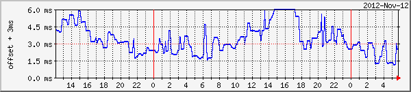
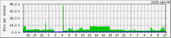
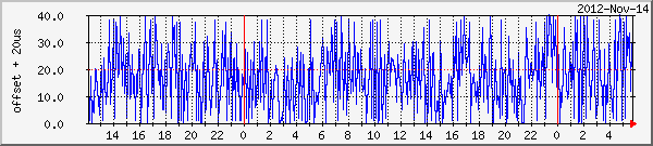
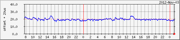
graphs are not all to the same vertical scale! Offset using Internet servers alone - millisecond scaleThe resulting performance is good, but it will depend on both the loading of the link between me and the ISP, and the general load on the ISP's network and the general Internet. Offsets are reported to be with about +/-5 milliseconds (and therefore off-scale once on the graph below). The four-line ntp.conf in use at the time is shown below the graph.
# Drift file to remember clock rate across restarts
driftfile /var/lib/ntp/ntp.drift
# Servers
pool uk.pool.ntp.org iburst
|
 |
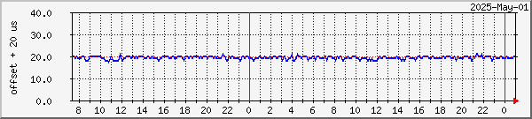
Raspberry Pi #1 512 MB, Linux/3.2.27+ LAN sync precision scale |
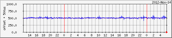 |
Same data but on a microsecond scale |
# Drift file to remember clock rate across restarts
driftfile /var/lib/ntp/ntp.drift
# Servers
server 192.168.0.3 minpoll 5 maxpoll 5 iburst prefer
server 192.168.0.2 minpoll 5 maxpoll 5 iburst
server 192.168.0.7 minpoll 5 maxpoll 5 iburst
pool uk.pool.ntp.org minpoll 10 iburst
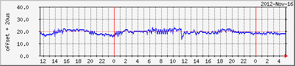
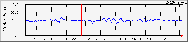
Much better results are obtained using a Trimble Resolution SMT GPS module, with its PPS pin connected to the GPIO 24 pin for a kernel-mode "ATOM" ref-clock. This unit is a "timing" GPS, with 15 ns specified accuracy for the PPS signal. Each second pulse on the GPIO pin causes an interrupt in which the CPU clock is noted, and then used by NTP to make fine adjustments to the software clock speed. The transients of a few microseconds amplitude lasting for about an hour may be due to sudden ambient temperature changes affecting the crystal used by the card's clock generator. Not shown on the graph, but the offset due to a CPU-heavy task (recompiling NTP from source, taking about 25 minutes) resulted in a 20 �s positive excursion, followed by a 10 �s negative excursion as temperatures cooled and NTP recovered.
 |
Raspberry Pi #1 512 MB, Linux/3.2.27+ Kernel PPS sync Trimble Resolution SMT timing GPS receiver |
When using a u-blox MEO-6M GPS module, with its PPS pin connected to the GPIO 24 pin for a kernel-mode "ATOM" ref-clock, similar results are obtained. The transient in the middle of the graph is when a second device was connected to the 5 V line from the USB. This unit is a "navigation" GPS, where the PPS is specified about 100 ns, rather than a "timing" GPS - but the difference between the two units is most-often masked by the other variations in the system.
 |
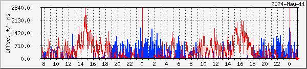
Raspberry Pi #1 512 MB, Linux/3.2.27+
Kernel PPS sync |
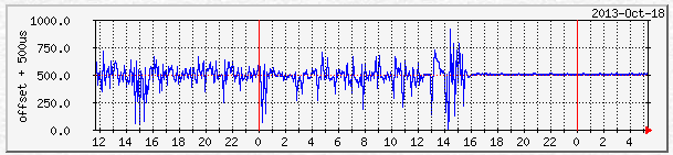
Later, it was noticed that the offset was varying periodically, and this is an unexpected result. Below is a sample from 2012 Dec 19-21, with the less stable period staring at the end of 2012-Dec-19 and finishing at the end of Dec 20. More detailed examination of the loopstats data shows an actual period of just over 100 seconds, and it's being aliased by the 5-minute sampling of MRTG.
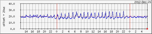 |
Raspberry Pi #1 512 MB, Linux/3.2.27+
Kernel PPS sync |
To test, I had changed the GPS receiver from U-blox 6M to Adafruit MTK3339
navigation GPS module, and later changed again from the navigation module to
a timing GPS module based on the U-blox
LEA-6T, to see whether the oscillation was affected. These changes
made no difference to either the magnitude and the period of the oscillation,
and the amplitude of the oscillation was considerably greater than what would be
expected even from a "navigation" GPS receiver. So my earlier
theories about navigation versus timing GPS modules, USB loading, and serial I/O
loading were incorrect. This problem was eventually cured by a firmware
update on Raspberry Pi #1, from version 337601 to version 346337.
I added a second Raspberry Pi computer and now have both connected to the two different GPS/PPS receivers mentioned above, but with the antennas for those receivers in a similar indoor location. Below is a comparison of the performance. Raspberry Pi #1 is located in an unheated room with a north-facing wall. Raspberry Pi #3 is also in the office, but situated a little nearer to a radiator, providing the daily transients. In mid-November 2013 I moved to a new kernel which was locally compiled with an option to improve NTP performance.
 |
Raspberry Pi #1 512 MB, Linux/3.6.11 Kernel-mode PPS sync Adafruit MTK3339 navigation GPS receiver in unheated room |
 |
Raspberry Pi #3 512 MB, Linux/3.6.11 Kernel-mode PPS sync U-blox 6M navigation GPS receiver in office environment |
 |
Raspberry Pi #4 512 MB, Linux/3.6.11 Kernel-mode PPS sync U-blox 5S navigation GPS receiver in unheated room |
 |
Raspberry Pi #5 512 MB, Linux/3.6.11 Kernel-mode PPS sync U-blox 7Q timing GPS receiver in office environment |
 |
Raspberry Pi #1 512 MB, Linux/3.6.11 Kernel-mode PPS sync Adafruit MTK3339 navigation GPS receiver in unheated room |
 |
Raspberry Pi #3 512 MB, Linux/3.6.11 Kernel-mode PPS sync U-blox 6M navigation GPS receiver in office environment |
 |
Raspberry Pi #4 512 MB, Linux/3.6.11+ Kernel-mode PPS sync U-blox 5S navigation GPS receiver in unheated room |
 |
Raspberry Pi #5 512 MB, Linux/3.6.11+ Kernel-mode PPS sync U-blox 7Q timing GPS receiver in office environment |
You can buy an SD card with the Linux OS installed and ready to go. As I knew I would need to make modifications to the OS I did buy a ready-programmed SD card just in case, but I made my own by following the steps here: http://www.raspberrypi.org/downloads
I then plugged in the SD card to the Raspberry Pi, connected it to the network, and applied power...
Many folk have asked about adding a GPS to the Raspberry Pi without needing soldering, and now that has become a reality thanks to the NTPI GPS Addon Board produced by Nevis Computers Ltd in the UK. I used the rpi_gpio_ntp program was developed by Folkert van Heusden and announced in the Time-Nuts mailing list, which allows user-mode working with the PPS signal, thus not requiring a special version of the operating system. Current versions of Raspbian no longer need this.
This is what you get in the box for the NTPI Raspberry Pi GPS Addon Board (with the puck antenna option):
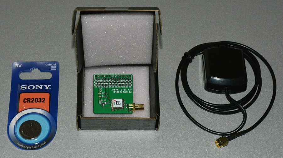
(Note that the antenna is an optional extra, and you need to buy
your own battery)
To get this working with a Raspberry Pi, these are the steps I took. I've included the steps to add MRTG monitoring and remote file access from Windows systems, but you may omit those if you don't need them.
| Installed onto the Raspberry Pi the card looks like this. The antenna lead can be taken out through a hole in the case near the Ethernet connector. Note that this board uses |
 |
How well does this user-mode work, you may ask. Well it's pretty good, although not quite as good as kernel-mode, but more than adequate for the precision offered by the Raspberry Pi. Perhaps the best that the Pi could do otherwise would be syncing over a LAN connection to a stratum-1 NTP server. The offset plot comparison below shows the Pi synced to a stratum-1 server but over Wi-Fi, and then the performance after installing the NTPI GPS Addon board. An ideal plot would be a straight line at the 500 microsecond level on this graph (I have to add an offset as MRTG can't plot negative numbers). The 6-hour averaged jitter reported by NTP dropped from 100-150 microseconds to under 4 microseconds. The improvement in going from Wi-Fi sync to PPS sync is obvious!
The version of Linux you are running is displayed when you log in, but you can also use the command:
$ uname -a
to show what version is running. I started with:
Linux raspberrypi 3.12.26+ #702 PREEMPT Wed Aug 6 17:43:49 BST 2014 armv6l GNU/Linux
To update my software, I ran the commands:
$ sudo apt-get update
$ sudo apt-get dist-upgrade
$ sudo rpi-update
and after rebooting I ended with:
Linux raspberrypi 3.12.32+ #721 PREEMPT Fri Nov 7 16:50:31 GMT 2014 armv6l
Thanks to e-mails from Olav Andrarde and Timo Kokkonen I have discovered that PPS support has now been added to the Linux available for the Raspberry Pi, although you do need to add a couple of lines to the configuration to enable it. As Raspbian in continually evolving, the exact method for making these changes also evolves, so depending on when you downloaded Raspbian you should follow either the November 2014 or the February 2015 sections below. I've put the more recent information first, although I normally prefer things to be listed in chronological order like in a diary!
After updating another Raspberry Pi to the most recent Raspbian - for a new Raspberry Pi 2 which I had purchased - I discovered that things had changed once again. These details from my quick-start page. Linux versions: 3.18.6+ 3.18.7-v7
$ sudo nano /boot/config.txt
- Add dtoverlay=pps-gpio,gpiopin=18
on a new line.
If you previously added bcm2708.pps_gpio_pin=18 to the end of
cmdline.txt, remove it.
Save and close.
$ sudo nano
/etc/modules � Add pps-gpio
on a new line.
Save, close & reboot.
Now proceed to check that PPS is working.
There are two steps required to enable PPS on the GPIO port, one to tell the kernel to include the support, and one to actually cause the support module to be loaded. First, tell the kernel that GPIO pin 18 is to be used. This enables the PPS-GPIO support in the kernel. Add this text to the /boot/cmdline.txt file:
$ sudo nano /boot/cmdline.txt
add:
bcm2708.pps_gpio_pin=18
to the end of the line.
It must be on the same line, not on a new line,
as Ray Hunter found out!
Next, you need to tell the kernel to load the module which provides this support. Quite why this can't be automatic I don't know! Add the module name to the end of the file /etc/modules.
$ sudo nano /etc/modules
add:
pps-gpio
at the end if the list, and reboot.
To check that the module is loaded, you can use the lsmod command, for example:
$ lsmod | grep pps
The output should be similar to:
pps_gpio 2529 1
pps_core 7943 2 pps_gpio
You should now be able to run the ppstest command and see the transitions once per second, for example:
$ sudo ppstest /dev/pps0 # press Ctrl-C to cancel..
trying PPS source "/dev/pps0"
found PPS source "/dev/pps0"
ok, found 1 source(s), now start fetching data...
source 0 - assert 1351501153.999956346, sequence: 47481 - clear 0.000000000, sequence: 0
source 0 - assert 1351501154.999954601, sequence: 47482 - clear 0.000000000, sequence: 0
source 0 - assert 1351501155.999951856, sequence: 47483 - clear 0.000000000, sequence: 0
^C
Note that there is no value given for the "clear" time. Gary
E Miller reports that the pps-gpio driver only looks for one edge, the positive
going edge. If you are using a different GPS device from those mentioned
here you may need to a 3.3 volt output inverter in the PPS line from the GPS.
Historical information only: Since I first wrote this page, Hauke Lampe has made available a pre-configured Raspberry Pi OS image here. His write-up is based on his version of a serial GPS as I describe here, but you need do none of the building and configuration work I mention here. My Raspberry Pi #3 is running from this OS image, and I'm developing the GPS installation at the moment. The comments and changes so far:
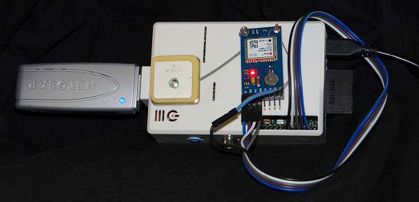
Quite a few of the "standard" Raspberry Pi utilities are not present in this OS image, and will need to be downloaded separately with apt-get. Here's what it looks like at the moment. The patch antenna is attached to the white ModMyPi case with double-sided sticky tape, and the receiver board with a single nut and bolt. The leads were also from ModMyPi, and the 150 mm length is not required here! The Wi-Fi dongle is on the left. Performance graphs are here.
As my trial application is for an NTP server, I don't need a display on the Raspberry Pi, or for that matter a keyboard and mouse permanently connected. All my interaction will be via a terminal, and even that will be emulated via program running on a remote PC, with connectivity through the Ethernet port on the Raspberry Pi. Such operation is commonly called a headless server. A power supply and case were the only items I added to the as-supplied Raspberry Pi. There is some advice on running headless here: http://glynrob.com/hardware/raspberry-pi-headless/
You need a terminal program which will work in SSH mode - I used PuTTY on a Windows XP PC.
I watched on my router which runs DD-WRT to see the IP address which had been assigned to the Pi, and I then used that address to run PUTTY in SSH mode. I got a connection right away with the default user name and password. You can save the settings for the Pi from within PUTTY (I called mine "RaspberryPi"), and make a Windows shortcut to connect to your Pi with values such as:
Target:   C:\Tools\PuTTY\PUTTY.EXE -load RaspberryPi
Start in: C:\Tools\PuTTY
Your path and saved settings name will be different.
Linux command to disconnect and logout: logout
By the way, by adding an X-windows server
program such as Xming to your PC you can see the graphics from the Raspberry Pi
as well, should you wish, but that's not required for the operations described
here - you can do everything directly from the command-line.
I followed the advice here to update the OS, although I don't think that it was really necessary as the OS downloaded was only a month old. To run the commands requires privileged access, achieved here by prefixing the command with sudo. These commands take considerable time to run, and require Internet access from your Pi. Allow 30 - 45 minutes.
$ sudo apt-get update
$ sudo apt-get dist-upgrade
You are likely to need to restart the OS after making these changes:
$ sudo reboot
If you want to determine what upgrades are pending, try:
$ sudo apt-get --just-print upgrade
and redirect the output to a text file. Thanks to Graham
in County Durham, UK, for that tip.
You may want to check that the Raspberry Pi is configured to give you the time in your local time zone: Use the command:
$ sudo dpkg-reconfigure tzdata
and select the appropriate region and town. For the UK,
I selected Europe/London. The procedure will reflect the timezone data and
current date and time in both the local time and UTC when it completes.
Although there is a graphical interface with which to configure the Wi-Fi, it didn't seem to work for me. In any case, if you are operating headless, you may not even have access to the GUI. The network adapter I used was the tiny Edimax EW-7811UN 150Mbps Wireless Nano USB Adapter unit, which I got from Amazon (fair price and good delivery).
There appear to be three steps:
You can then use the $ sudo ifdown
wlan0 and $ sudo ifup wlan0 commands to
restart the wireless networking. I would also advise a reboot to ensure
that everything has gone as expected.
The NTP configuration file lives in the /etc directory, so you can change to that directory to edit the file. Because the file is a system file, you need to sudo command to allow to save the edited version of the file, but first, I made a copy (cp) of the supplied file just in case I messed up and had to revert to the working NTP configuration. I used the vi editor which is supplied with the OS, and there are instructions for vi here, and also at Guru99.com as part of a Linux/Unix tutorial for beginners. The nano editor which I discovered later, and which is supplied with the Raspberry Pi, is a much better choice - much easier to use!
$ cd /etc
$ sudo cp ntp.conf ntp-original.conf
$ sudo nano ntp.conf
I wanted to be able to monitor NTP from another PC on my LAN, rather than adding the MRTG monitoring program to the Pi, however there are lines which restrict access to the NTP running on the Pi in its default installation. These lines in the ntp.conf file start with the keyword "restrict". I removed these restrictions by commenting out these lines - which is achieved by adding a hash character at the start of the line. For example:
Replace:
    restrict -4 default kod notrap nomodify noquery

With:
    # restrict -4 default kod notrap nomodify noquery
After changing ntp.conf, you need to restart the ntp daemon:
$ sudo /etc/init.d/ntp restart
If you were concerned about security on your LAN you might
wish to be more selective in making changes to the restrictions.
While the default ntp.conf contents will work correctly for most purposes, they do not take advantage of the new NTP POOL directive to specify pool servers. I also altered the generic "debian" pool to the more local "UK" pool. I therefore changed the server pool. lines to a single pool directive:
Replace:
    server 0.debian.pool.ntp.org iburst
    server 1.debian.pool.ntp.org iburst
    server 2.debian.pool.ntp.org iburst
    server 3.debian.pool.ntp.org iburst
With: pool uk.pool.ntp.org iburst
My own LAN has three stratum-1 NTP servers, one on FreeBSD and two running Windows, so I added those before the pool servers. Of course, this is specific to my LAN. For the minimum offset, I made NTP poll the local servers at 32 (2^^5) second intervals, and did not allow that to drift upwards towards the 1024 seconds maximum interval that NTP would reach left to its own devices. I did this with the minpoll and maxpoll qualifiers. However, I did not want to force the Internet servers to be interrogated that often (it is considered at best impolite, and at worst could get you blocked from a server), so I therefore made the minimum polling interval for the Internet servers 1024 seconds (2^^10). I removed things which had been commented out to simplify the file, and make it easier to understand. Hence my ntp.conf ended up as follows:
# /etc/ntp.conf, configuration for ntpd; see ntp.conf(5) for help

# Drift file to remember clock rate across restarts
driftfile /var/lib/ntp/ntp.drift

# Servers
server 192.168.0.3 minpoll 5 maxpoll 5 iburst prefer
server 192.168.0.2 minpoll 5 maxpoll 5 iburst
server 192.168.0.7 minpoll 5 maxpoll 5 iburst
pool uk.pool.ntp.org minpoll 10 iburst
Remember to restart NTP after making the changes. From a Windows monitoring PC with NTP installed I now see:
C:\>ntpq -p raspi
     remote           refid      st t when poll reach   delay   offset  jitter
==============================================================================
*pixie           .PPS.            1 u   26   32  377    0.467   -0.010   0.023
+feenix          .PPS.            1 u    4   32  377    0.603   -0.226   0.039
+stamsund        .PPS.            1 u   31   32  377    0.586    0.004   0.040
-dns0.rmplc.co.u 193.62.22.74     2 u  707 1024  377   21.915    3.490   2.295
-dns1.rmplc.co.u 193.62.22.74     2 u  177 1024  377   23.736    4.609   3.621
-dawn.rt.uk.eu.o 193.79.237.14    2 u  277 1024  377   20.508    3.150   3.065
-lyla.preshweb.c 129.215.42.240   3 u  544 1024  377   28.082    5.937   3.944

C:\>ntpq -c rv raspi
associd=0 status=0615 leap_none, sync_ntp, 1 event, clock_sync,
version="ntpd 4.2.6p5@1.2349-o Fri May 18 20:30:57 UTC 2012 (1)",
processor="armv6l", system="Linux/3.2.27+", leap=00, stratum=2,
precision=-20, rootdelay=0.467, rootdisp=2.387, refid=192.168.0.3,
reftime=d4365966.98133154  Sat, Oct 27 2012 14:00:22.594,
clock=d4365984.f4e4138b  Sat, Oct 27 2012 14:00:52.956, peer=49569, tc=5,
mintc=3, offset=-0.010, frequency=-43.888, sys_jitter=0.023,
clk_jitter=0.015, clk_wander=0.008
One approach towards getting NTP to see the serial part of the GPS receiver output stream (for the coarse part of the time, the seconds) is to install the gpsd driver, and this does allow some checking of the basic connectivity. The GPS I started using was a Trimble Resolution SMT, for which I managed to get both an evaluation board and an interface board which converted the serial output into both RS-232 and USB. I used the serial over USB rather than the RS-232 for the Raspberry Pi.
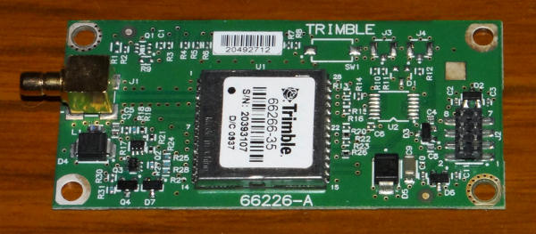 |
This is the GPS I used. It is an evaluation board for a timing GPS surface-mount receiver, the Trimble Resolution SMT. This is slightly unusual in having a TSIP-format output rather than the standard NMEA format, but the Linux gpsd can recognise and accept that format. The output is on an 8-pin header with a non-standard pin spacing! It's sensitive enough that I could use a magnetic mount GPS puck in my upper floor computer room. |
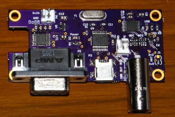 |
Just as I acquired the board,
there was an offer on the time-nuts mailing list for a
ready-made interface. This has a matching 8-pin connector, and
provides a PPS output, serial output at RS-232 levels (not used here), and has a built-in serial to USB converter! Ideal!
Do be careful in using other GPS units that you don't exceed +3.3 V on the PPS signal fed to the Raspberry Pi, as a 5 V signal level will damage the device. I used a resistive divider (not shown) to reduce the level to a nominal 3.2 V. I soldered a 3k9 * + 6k8 resistive divider to the PPS
header, and then soldered a twin lead fed to a 0.1-inch header I happened to have lying around.
This I connected to pins
GND and GPIO-24 on the 26-pin Raspberry Pi GPIO
header. |
First, I connected the device to the lower USB port, and then checked what was seen on the USB ports.
$ sudo lsusb
Bus 001 Device 001: ID 1d6b:0002 Linux Foundation 2.0 root hub
Bus 001 Device 002: ID 0424:9512 Standard Microsystems Corp.
Bus 001 Device 003: ID 0424:ec00 Standard Microsystems Corp.
Bus 001 Device 005: ID 04d8:00df Microchip Technology, Inc.
It seems that my GPS is appearing as 005 in that list, but what will it be named? To check this, you need to look through one of the Linux log files:
$ more /var/log/syslog
and in my case about the time I plugged in the device there was a reference to: ttyACM0:, and I recognised tty as a serial port (TeleType from long ago!). If you are using a real serial device it will appear as ttyAMA0.
The next steps are to install the gpsd software, and start the gpsd service pointing to the device name just discovered:
$ sudo apt-get install gpsd gpsd-clients python-gps
From one report I had received, if you get errors with the above step you may need to run an update to apt-get:
$ sudo apt-get update
and possibly then:
$ sudo apt-get upgrade
which may upgrade the entire OS to the current version.
$ sudo gpsd /dev/ttyACM0 -n -F /var/run/gpsd.sock
At this point, you should be able to see a text-mode output from your GPS receiver by running the command "cgps -s", something like the following.
$ cgps -s
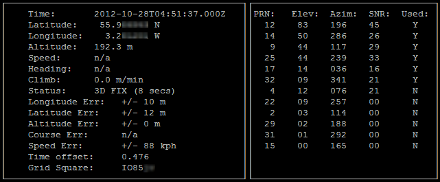
Note that as this is a timing-mode GPS, it will prefer
satellites which have a higher elevation, as these are less likely to have
multi-path effects or reflections. However, for the level of accuracy for
which we are aiming (microseconds, not nanoseconds), this refinement is not
essential, and I could see no significant difference between a
"timing" GPS and a "position" GPS on the microsecond level.
Note that you will need to make gpsd start automatically at boot time,
and to tell the configuration tool what device to use, and add the "-n"
option for working with NTP. See the note later in this
document.
Now that gpsd is working, we can edit the NTP configuration to add a type 28 reference clock which will make NTP look at the shared memory created by gpsd. This can be done for both the coarse time (seconds) and the fine time (PPS edge) with a 28.0 and a 28.1 driver, although I only use the 28.0 driver here as the Raspberry Pi supports PPS via a kernel-mode driver (more later). The first step is to get the seconds alone, and be aware that this will not be better than Internet time alone due to the offset of the serial/USB data from the true second, and because of the variability and drift in this offset. We will need to add a connection later between the PPS signal and one of the Raspberry Pi's I/O pins to generate a PPS interrupt. Here is my modified ntp.conf file. I've used 0.000 for the time1 modifier to start with, so that we can determine an approximate value for the delay of the serial data from the GPS after ntp is up and running. I changed the refid for the type 28 driver to "SHM" to indicate more clearly that the data is coming from the SHared Memory provided by gpsd.
Note that I have marked more than one server as "prefer". This is because if the first preferred server goes offline, it appears that NTP will no longer accept the PPS data as valid (is that wise?), so a second preferred server is configured to cover that possibility. In my case, it happens because 192.168.0.3 sometimes has an NTP update, causing its NTP to go offline for some seconds, and hence causes a glitch in the connected servers. Having more than one preferred server should prevent that.
# /etc/ntp.conf, configuration for ntpd; see ntp.conf(5) for help

# Drift file to remember clock rate across restarts
driftfile /var/lib/ntp/ntp.drift
# Server from shared memory provided by gpsd server 127.127.28.0 minpoll 4 maxpoll 4 prefer fudge 127.127.28.0 time1 0.000 refid SHM stratum 15# Local LAN servers server 192.168.0.3 minpoll 5 maxpoll 5 iburst prefer server 192.168.0.2 minpoll 5 maxpoll 5 iburst prefer server 192.168.0.7 minpoll 5 maxpoll 5 iburst prefer# UK pool servers pool uk.pool.ntp.org minpoll 10 iburst
Note that when using a PPS source you must have one other server marked "prefer". In the example above I have added prefer to the shared memory driver (type 28) so that the combination of PPS and GPSD would provide the correct time even with no Internet servers. Looking at the output from ntpq -p after some time we might see:
C:\>ntpq -p raspi
     remote           refid      st t when poll reach   delay   offset  jitter
==============================================================================
xSHM(0)          .SHM.           15 l   15   16  377    0.000  -353.23   1.277
*pixie           .PPS.            1 u   25   32  377    0.484   -0.016   0.105
+feenix          .PPS.            1 u   31   32  377    0.592   -0.120   0.044
+stamsund        .PPS.            1 u   16   32  377    0.546   -0.037   0.083
xns0.luns.net.uk 157.44.176.4     2 u 1656 1024  156   31.904    3.702   5.455
xtime.videxio.ne 131.188.3.223    2 u  45m 1024   74   31.765    8.590   2.796
xlyla.preshweb.c 129.215.42.240   3 u  510 1024  377   25.568    4.793   5.990
-dawn.rt.uk.eu.o 193.67.79.202    2 u  492 1024  367   20.308    2.408   2.903
and while the SHM driver is present and connected (reach = 377), it has been rejected by NTP (the "x" in the first column), perhaps because its offset was consistently too great compared to the other servers. That's the purpose of the time1 modifier in the "fudge" command. We can see that the SHM output is some 350 milliseconds later, so we can use that value for time1 to bring the GPS output approximately into line with UTC, as shown in the edited /etc/ntp.conf below. (The time values in the ntpq -p display are all in milliseconds).
Hint: if at this point the reach field for the SHM device stays at zero, likely the gpsd wasn't started with the "-n" option. You can make the gpsd always start at system boot time with that -n option as described later in this note.
# /etc/ntp.conf, configuration for ntpd; see ntp.conf(5) for help

# Drift file to remember clock rate across restarts
driftfile /var/lib/ntp/ntp.drift
# Server from shared memory provided by gpsd server 127.127.28.0 minpoll 4 maxpoll 4 fudge 127.127.28.0 time1 +0.350 refid SHM stratum 15# Local LAN servers server 192.168.0.3 minpoll 5 maxpoll 5 iburst prefer server 192.168.0.2 minpoll 5 maxpoll 5 iburst server 192.168.0.7 minpoll 5 maxpoll 5 iburst# UK pool servers pool uk.pool.ntp.org minpoll 10 iburst
The output from ntpq -p then shows the offset for the SHM driver to be much nearer to zero, and this /might/ be good enough for you if you are out in the field with no other reference. But we can do better, and the next step is to use the precise PPS signal from the GPS to improve the accuracy down to the microsecond level.
C:\>ntpq -p raspi
     remote           refid      st t when poll reach   delay   offset  jitter
==============================================================================
-SHM(0)          .SHM.           15 l    1   16   17    0.000    1.766   0.943
*pixie           .PPS.            1 u   13   32    3    0.421   -0.325   0.194
+feenix          .PPS.            1 u   13   32    3    0.528   -0.644   0.969
+stamsund        .PPS.            1 u   11   32    3    0.409   -0.336   0.145
-dns0.rmplc.co.u 195.66.241.2     2 u   35 1024    1   22.872    3.604   5.037
-mail1.itdojo.or 10.10.120.2      2 u   34 1024    1   38.472    3.324   7.084
 ntp.fundamental 193.62.22.82     2 u   33 1024    1   30.980    2.450   3.837
 82.113.154.206  193.62.22.82     2 u   32 1024    1   19.219    0.683   5.880
Note: if you are working stand-alone, without any Internet servers, you may need an extra "flag1 1" in the fudge for the type 28 ref-clock. Please see the notes here for further information. Thanks to Whitham D. Reeve Anchorage, Alaska USA for the testing.
I did notice with the GPS unit that I have that it doesn't have battery backup, so when it first starts it has to download quite a lot of data from the GPS satellites before it has full lock. While the PPS signal is acquired quite quickly, it takes a few minutes for the receiver to determine the number of seconds offset between GPS-time GPST) and the usual UTC. As I write, that GPST-UTC offset is 16 seconds - the offset is because recent leap-seconds are not applied to GPS time - more information. The implications of this are different depending on what other servers you have configured in your ntp.conf file
Quite why I saw this issue while using gpsd is uncertain. Since writing the above I have been in contact with the author of gpsd who tells me that protection is incorporated into the gpsd software whereby it will not pass on the time to its shared memory until the output from the GPS receiver has a (GPST-UTC) value in excess of 10 seconds. So I should never have seen the 16 seconds faster value at all.
Please note that this problem is likely peculiar to my
particular GPS receiver - an
evaluation board with no battery backup. Just be aware of this problem in
case it bites you! It doesn't happen with the u-blox pure serial GPS
receiver I describe later, as this board has battery
backup. "Your mileage may vary", as they say!
The next step was to get the PPS working. This requires updating the Linux kernel for the Raspberry Pi, and while you can do that yourself, there is a ready-made kernel image and support modules available on the Web. Much of the information below is based on David K's Web page:
https://github.com/davidk/adafruit-raspberrypi-linux-pps
You can check the version of the kernel you are running at the moment by:
$ uname -a
Linux raspberrypi 3.2.27+ #250 PREEMPT Thu Oct 18 19:03:02 BST 2012 armv6l GNU/Linux
First you need to get the updated kernel image and modules. At the time of writing, these were available for the current version of the OS from chrisprt as mentioned here:
Kernel image: https://docs.google.com/open?id=0BznvtPCGqrd3ZElKZHEtUDRpUEU
Modules: https://docs.google.com/open?id=0BznvtPCGqrd3VTZ2TmxFTktYM0E
These come down as Zip files and, as I wasn't sure about downloading these from Google Docs directly on the Raspberry Pi, I downloaded them to a local Windows FTP server first, and then installed an FTP client on the Raspberry Pi to drag the Zip files across in FTP image mode - i.e. binary files.
# Installing an FTP client:
$ sudo apt-get install ftp
I could then use standard FTP command to drag the files from my local FTP server to the Raspberry Pi. I created a directory named pps below the home user directory for the files, and then unzipped the archives I had copied:
$ mkdir pps
$ cd pps
# FTP get 3.2.27-pps-g965b922-dirty.zip in binary (image) mode.
# FTP get kernel-pps-gpio24.zip in binary (image) mode
(substitute your own commands here).
$ unzip kernel-pps-gpio24.zip
$ unzip 3.2.27-pps-g965b922-dirty.zip
In the pps/kernel-pps-gpio24 directory you will find a file kernel-pps-gpio24.img. This must be renamed and moved to the /boot/ directory, while we first take a safety copy of the original kernel image.
$ sudo mv /boot/kernel.img /boot/kernel.img.orig
$ sudo cp kernel-pps-gpio24.img /boot/kernel.img
Now we need to move the module files into the area where the new kernel expects to find them. I found the command on the Web page either confusing or wrong, as I ended up with the wrong structure to start with. What it appears to need is:
/lib/modules/3.2.27+
/lib/modules/3.2.27+/kernel
/lib/modules/3.2.27+/modules.*
/lib/modules/3.2.27-cutdown+ /lib/modules/3.2.27-cutdown+/kernel /lib/modules/3.2.27-cutdown+/modules.*/lib/modules/3.2.27-pps-g965b922-dirty /lib/modules/3.2.27-pps-g965b922-dirty/kernel/ /lib/modules/3.2.27-pps-g965b922-dirty/modules.*
You will find both the kernel directory and the modules files in the unzipped 3.2.27-pps-g965b922-dirty directory, so the following command may work correctly for you. I made a mess of this having followed the Web page verbatim, and not having made allowances for the differences in the file name. Assuming you are now in the pps directory, move the required files to the /lib/modules directory, and add the pps-gpio module to the module list:
$ sudo mv 3.2.27-pps-g965b922-dirty /lib/modules/3.2.27-pps-g965b922-dirty
$ echo "pps-gpio" | sudo tee -a /etc/modules
(Command corrected, thanks Matthew Huxtable!  Alternatively edit
 /etc/modules using the nano editor to add the pps-gpio at the end.
$ sudo nano /etc/modules
$ sudo reboot
You will see the changed kernel name at the next login, and you can check with the uname -a command as before:
$ uname -a
Linux raspberrypi 3.2.27-pps-g965b922-dirty #1 PREEMPT Sat Sep 22 16:30:50 EDT 2012 armv6l GNU/Linux
You may be used to the idea of device drivers for Windows - those .SYS files - but what are "modules" in Linux and how do they relate to device drivers? I asked that question on the time-nuts list, and got this reply from Michael Tharp:
"Linux modules are the same, although Linux modules almost always need to be compiled against the specific kernel version while Windows drivers are typically only bound to which release you're running. That is the reason you have to compile the kernel, rather than just plop down a driver downloaded from the internet.
"That said, the reason your PPS driver is a module is that it makes it easier to tweak options. Almost all modules that are part of the main kernel source (which PPS is, for a year or so) can be compiled in rather than as a separate module, but you can pass options to a module as you load it while you cannot do that with a built-in. It also makes it possible to tweak the source, recompile just that module, and test it on the fly rather than recompiling the entire kernel and rebooting."
Many thanks, Michael.
To check that you are running the new kernel and that the pps-gpio module is loaded, then install the pps-tools and run it to see the changes on pin 24 (assuming you have a 3.3 V PPS signal connected. Warning: do not connect a 5 V signal to the GPIO pins!
$ uname -a
Linux raspberrypi 3.2.27-pps-g965b922-dirty #1 PREEMPT Sat Sep 22 16:30:50 EDT 2012 armv6l GNU/Linux
$ dmesg | grep pps
[ 0.000000] Linux version 3.2.27-pps-g965b922-dirty (root@bt) (gcc version 4.
6.2 (Ubuntu/Linaro 4.6.2-14ubuntu2~ppa1) ) #1 PREEMPT Sat Sep 22 16:30:50 EDT 20
12
[ 1.866364] usb usb1: Manufacturer: Linux 3.2.27-pps-g965b922-dirty dwc_otg_h
cd
[ 12.797224] pps_core: LinuxPPS API ver. 1 registered
[ 12.803850] pps_core: Software ver. 5.3.6 - Copyright 2005-2007 Rodolfo Giome
tti <giometti@linux.it>
[ 12.824858] pps pps0: new PPS source pps-gpio.-1
[ 12.832182] pps pps0: Registered IRQ 194 as PPS source
[ 133.043038] pps_ldisc: PPS line discipline registered
[ 133.044841] pps pps1: new PPS source acm0
[ 133.044879] pps pps1: source "/dev/ttyACM0" added
$ sudo aptitude install pps-tools # may take some time
$ sudo ppstest /dev/pps0 # press Ctrl-C to cancel..
trying PPS source "/dev/pps0"
found PPS source "/dev/pps0"
ok, found 1 source(s), now start fetching data...
source 0 - assert 1351501153.999956346, sequence: 47481 - clear 0.000000000, sequence: 0
source 0 - assert 1351501154.999954601, sequence: 47482 - clear 0.000000000, sequence: 0
source 0 - assert 1351501155.999951856, sequence: 47483 - clear 0.000000000, sequence: 0
^C
The "clear" entries showing as zero is correct for
this driver implementation. Note that if you don't have a PPS signal
connected to GPIO pin 24 the last three lines from the dmesg output may be
missing. In the output above, the PPS source was only registered some 133
seconds after startup, possibly the length of time it took the GPS to
lock. On a second system with no PPS connected the last three lines were
missing.
This test should still work even with NTP running and using the PPS signal.
Unfortunately, the version of NTP supplied with the Raspberry Pi Linux does not support PPS. Likely it has been compiled to minimise its memory and disk footprint. These are the steps to download, compile and install NTP (with help from jbeal's posting). You can choose between a release and a development version as shown in step 4 below. You could also use a copy of the development tarball on your own local FTP server. So from logging in, here are the steps. The lines below are shown for development version ntp-dev-4.2.7p397, but you will need to alter the version number to suit the version you wish to compile. The two time-consuming steps (configure and make) appear to be CPU limited rather than SD-card I/O access limited. You can see which version I am currently running here.
$ mkdir ntp # make a convenient working directory, if you don't already have one
$ cd ntp # enter that directory
$ sudo apt-get install libcap-dev	# once-off, required to prevent later file not found error
$ sudo apt-get install libssl-dev	# once-off, you may not need this, but reports suggest you might to build keygen
# Get the desired tarball, current or development - use one of the following:
$ wget http://archive.ntp.org/ntp4/ntp-4.2/ntp-4.2.8p10.tar.gz					# release
$ wget http://archive.ntp.org/ntp4/ntp-dev/ntp-dev-4.2.7p397.tar.gz			# development

(May redirect to:  https://www.eecis.udel.edu/~ntp/ntp_spool/ntp4/ntp-4.2/ntp-4.2.8p10.tar.gz)
$ tar xvfz ntp-4.2.8p10.tar.gz
$ cd ntp-dev-4.2.8p10
$ ./configure --enable-linuxcaps	# takes 11-15 minutes

# If your PPS doesn't work and you get a "clock type 22 invalid" message, be sure to install pps-tools
# first, and clear out the directory:  cd ~/ntp, rm -r ntp-dev-4.2.7p397, and start again from step 5.

# It seems that the --enable-linuxcaps flag may not be required on other Linux variants,
# or on the RPi with later versions of Linux with PPS and pps-tools installed.
# It is required for the more recent Raspbian Jessie (later 2015).
$ make					# takes 18-25 minutes
(use "make -j5" for faster execution on the four-core Raspberry Pi 2/3.)
# This removes the original NTP and installs the new.
# Step may not be needed - see below.
# Recommend: omit this step.
$ sudo apt-get remove ntp    # get rid of previously existing install of ntpd
$ sudo make install # puts ntp* in /usr/local/bin/ntp*, takes 30-60 seconds
It is not entirely clear to me whether step 9 above is required. It does not appear to be when updating from 4.2.7p304 to 4.2.7p321, for example. I am not using step 9.
Once you have a new set of NTP binaries, you first need to stop NTP, use super-user mode to copy the binaries to their final directory, and then restart NTP. Once restarted, a simple check that it's working correctly. I recommend these steps, although there are alternatives. See the note below about step 2.
$ sudo /etc/init.d/ntp stop
$ sudo cp /usr/local/bin/ntp* /usr/bin/ && sudo cp /usr/local/sbin/ntp* /usr/sbin/
$ sudo /etc/init.d/ntp start
$ ntpq -crv -pn # optional step to check for version and basic function
Note: on some more recent versions of Raspbian steps 1 and 3 may require:
$ sudo service ntp stop
$ sudo cp /usr/local/bin/ntp* /usr/bin/ && sudo cp /usr/local/sbin/ntp* /usr/sbin/
$ sudo service ntp start
Note: that on some systems the binary ntp* files will be written to a mixture of /usr/local/bin and /usr/local/sbin, according to the paths defined in sntp/loc. I have been told that the "sbin" is for system files (i.e. ones not usually run by users such as servers and daemons, and the "bin" is for files usually executed by users). For Debian, for just the ntp* files, this is:
# Debian installations and man page suffixes
MDOC
ntp-keygen,sbin,8
ntp-wait,sbin,8
ntpd,sbin,8
ntpdate,sbin,8
ntpdc,bin,1
ntpdsim,sbin,8
ntpq,bin,1
ntpsnmpd,sbin,8
ntptime,sbin,8
ntptrace,bin,1
so you may need to check both directories to get the most recent files. Check with "ls -l" which shows the file date.
A confession: I did alter one system to
point the NTP start-up to the directory I preferred, rather than leaving it
pointing to an old version. I suspect that in my own personal use, only
the ntpd and ntpq executables matter.
If, like me, you have multiple Raspberry Pi cards, you will not want to waste almost an hour compiling and updating NTP on each card. Fortunately, my experience so far using the development versions of NTP (4.2.7p...) suggests that simply copying the binaries from one Pi to another works as expected. This may be luck, or it may be because the OS differences between Linux/3.2.27+ and Linux/3.6.11+ are not that great. If you have access to an FTP server (I used a Windows PC running IIS) you may be able to use commands such as those below to save a compiled version from one Pi and load it onto another. You may need to use sudo apt-get install ftp if FTP is not already available. Step 5 is required once. Step 7 is required for each new version you save. Replace "368" in the steps below with the version number you have just compiled.
$ ftp <server-address-or IP>
(Login as Anonymous or known user)
bin (forces binary mode)
mkdir RaspberryPi (step only needed once)
cd RaspberryPi
mkdir 397-safe (step needed once per new version)
cd 397-safe
prompt (may disable prompting for steps 10 and 13)
lcd /usr/local/bin
mput ntp*
(respond Y to the prompt for all the files)
lcd /usr/local/sbin
mput ntp*
ls -l (to check that all eight files are there and have the date you expect)
quit
$ cd /usr/local/bin
$ sudo ftp <server-address-or IP> # sudo allows writing to system directories
(Login as Anonymous or known user)
bin (forces binary mode)
cd RaspberryPi/397-safe
ls -l (to check that the files there are correct and have the date you expect)
mget ntp*
(respond Y to the prompt for all the files)
quit
$ sudo /etc/init.d/ntp stop
$ sudo cp /usr/local/bin/ntp* /usr/sbin/ && sudo cp /usr/local/bin/ntp* /usr/bin/
$ sudo /etc/init.d/ntp start
$ ntpq -crv -pn # to check the NTP version, and that it is still working
See the discussion above about the combined commands in step 11. An alternative to steps 1 to 9 might be, if you are brave:
sudo wget -P /usr/local/bin -N ftp://<ftp-server-address>/RaspberryPi/397-safe/ntp*
After storing the working version on your FTP server, copy it on the FTP server to a directory with a fixed name such as:
/RaspberryPi/ntp/
You can then write a script for updating other Raspberry Pi cards something like this:
$ nano update-ntp
with the following contents:
sudo wget --no-passive-ftp -P /usr/local/bin -N ftp://<ftp-server>/RaspberryPi/ntp/ntp*
sudo /etc/init.d/ntp stop
sleep 1
sudo cp /usr/local/bin/ntp* /usr/sbin/  &&  sudo cp /usr/local/bin/ntp* /usr/bin/
sleep 1
sudo /etc/init.d/ntp start
sleep 4
ntpq -crv -pn
replacing <ftp-server> with the name or IP address of your own FTP server. With a Microsoft FTP server, I found that I needed to add --no-passive-ftp after the wget command, as shown above. Remember to make the script executable:
$ chmod +x update-ntp
and run it from your local directory:
$ ./update-ntp
You can tell another Raspberry Pi to run the update by using the SSH command thus:
$ ssh pi@the-other-raspi "./update-ntp"
You will need to enter the password for the user "pi", although
this can be avoided (I am told) by using public key based authentication, if that fits with your security model.
Once you have managed to copy your key to the second machine (man ssh-copy-id) you need no password either.
I'm afraid I don't know how to do that, though.
To get NTP to use the PPS data which is now available to it, the timestamps of the transitions on the GPIO pin, we need to add another refclock (server) line to the ntp.conf file. The server we use is a type 22 server called the ATOM refclock, and we can give it a reference ID of "PPS". I also changed the reference ID of the serial data to "GPS". Note that with a type 22 clock you must have one other server marked as "prefer".
# /etc/ntp.conf, configuration for ntpd; see ntp.conf(5) for help

# Drift file to remember clock rate across restarts
driftfile /var/lib/ntp/ntp.drift

# coarse time ref-clock, not really needed here as we have LAN & WAN servers
server 127.127.28.0  minpoll 4 maxpoll 4
fudge 127.127.28.0 time1 +0.350 refid GPS  stratum 15

# Kernel-mode PPS ref-clock for the precise seconds
server 127.127.22.0 minpoll 4 maxpoll 4
fudge 127.127.22.0  refid PPS

# LAN servers
server 192.168.0.3  minpoll 5 maxpoll 5 iburst prefer
server 192.168.0.2  minpoll 5 maxpoll 5 iburst
server 192.168.0.7  minpoll 5 maxpoll 5 iburst

# WAN servers, "pool" will expand the number of servers to suit
pool uk.pool.ntp.org  minpoll 10  iburst
Note: when using the ATOM (type 22) refclock, one of the other servers must be marked as prefer. This is because the type 22 clock only supplies the timing within the second, and another server is required to determine the current second.
When you have restarted NTP with the new binaries, you should see a new line in the output from an ntpq -p command, and the word "kern" should be present in the output of an ntpq -c rv command:
C:\>ntpq -p raspi
     remote           refid      st t when poll reach   delay   offset  jitter
==============================================================================
 SHM(0)          .GPS.           15 l   13   16  377    0.000   33.837   3.510
oPPS(0)          .PPS.            0 l   12   16  377    0.000    0.002   0.002
*pixie           .PPS.            1 u   18   32  377    0.498   -0.030   0.025
+feenix          .PPS.            1 u    5   32  377    0.619   -0.078   0.035
+stamsund        .PPS.            1 u   29   32  377    0.614   -0.017   0.051
 uk.pool.ntp.org .POOL.          16 p    - 1024    0    0.000    0.000   0.002
-ntp.uk.syrahost 192.93.2.20      2 u  405 1024  377   30.031    8.487   0.274
-ntp2.exa-networ 195.66.241.10    2 u  217 1024  377   26.263    3.167   1.277
-resntp-a-vip.lo 182.7.208.171    3 u   49 1024  377   17.854    2.828   1.460
-time.shf.uk.as4 91.208.177.20    3 u   75 1024  377   18.825    0.680   1.974

C:\>ntpq -c rv raspi
associd=0 status=011d leap_none, sync_pps, 1 event, kern,
version="ntpd 4.2.7p314@1.2483 Mon Oct 29 15:30:42 UTC 2012 (3)",
processor="armv6l", system="Linux/3.2.27-pps-g965b922-dirty", leap=00,
stratum=1, precision=-19, rootdelay=0.000, rootdisp=1.180, refid=PPS,
reftime=d439fe8b.16dba50f  Tue, Oct 30 2012  7:21:47.089,
clock=d439fe97.4d7ac44d  Tue, Oct 30 2012  7:21:59.302, peer=63905, tc=4,
mintc=3, offset=0.001547, frequency=-45.081, sys_jitter=0.001907,
clk_jitter=0.000, clk_wander=0.000
You may find that by adding the directive "nohz=off" to the end of your /boot/cmdline.txt that jitter is decreased by up to 50%. Try it and see for yourself. Some systems it helps, and others it does not, depending, I suspect, on which OS and firmware versions you have. As guide, you may get to average jitter in the range:
Model Averaged jitter Raspberry Pi B 3.9 us, but may be better Raspberry Pi B+ 4.2 �s Raspberry Pi 2 B 2 �s Raspberry Pi 3 B 1 �s
Thanks to the folks here
for their help.
With the replaced version of NTP we lose the automatic running of ntpd at startup which was present in the original install. We also need to start gpsd so that the coarse time is available to NTP.
# To configure gpsd to auto-start, try:
$ sudo dpkg-reconfigure gpsd
This seems to work as expected, and allows the gpsd to automatically start up. To check that, I rebooted, and logged in, and could run cgps -s right away. However, NTP won't see the time from the GPS until after cgps -s is run. This is fixed as follows (thanks to A Carver): by default, gpsd won't connect to the GPS receiver until there is client software such as cgps with requires it. This allows for some power-saving in the GPS receiver. To circumvent this, the gpsd needs to be started with the "-n" option. These options are set in the directory /etc/default, so you need to edit the file /etc/default/gpsd to change the line: GPSD_OPTIONS="" to GPSD_OPTIONS="-n". Method A is to do this through dpkg-reconfigure gpsd, method B is to edit the file directly.
$ sudo nano /etc/default/gpsd
NTP will auto-start after a reboot with either Method A or Method B above.
There is a cut-out area in the ModMyPi case which will allow connections to the GPIO connector such as ribbon cable which you can easily break out and file down to a neat edge. The sharp-eyed amongst you will notice that three wires are shown - this is because the surplus header had three wires connected, but I only used two - ground (blue) and GPIO 24 (red). The black lead would be GPIO 23 but it is unused and not connected.
There are two issues which are now becoming apparent with the particular GPS receiver I have and the Raspberry Pi.
If your receiver has this 16-second ambiguity, be sure you have a source
of coarse time available such as an Internet NTP server.
Because of the problem (1) above, I bought a serial GPS receiver from China. By following the instructions here I was able to make the serial port available on the Raspberry Pi independent of its use as a login or boot-up terminal port.
(make a safety coppy of the file we are about to edit)
$ sudo cp /boot/cmdline.txt /boot/cmdline_backup.txt
$ sudo nano /boot/cmdline.txt
(remove the parameter including the string "ttyAMA0":
console=ttyAMA0,115200
In Raspbian Wheezy there are two parameters:
 console=ttyAMA0,115200 kgdboc=ttyAMA0,115200)
$ sudo nano /etc/inittab
(Comment out the line like "2:23:respawn:/sbin/getty -L ttyAMA0 115200 vt100"
 by putting a hash (#) at the start of the line.  Note that the line was not
 2:23 on my version of Linux, so be sure to look for the actual line with ttyAMA0.
 It was the last line of the file, as it happens).
(You need to reboot to bring these changes into effect)
$ sudo reboot
(Minicom then works - to exit minicom, Ctrl-A, release, Q or X.)
$ minicom -b 9600 -o -D /dev/ttyAMA0
(If minicom gives command not found, you need to install it:)
$ sudo apt-get install minicom
Note that the Raspberry Pi requires 3.3 V signals on the serial
pins - not RS-232 level which will damage the device. You
should now be able to configure gpsd to talk to ttyAMA0 (using sudo
dpkg-reconfigure gpsd), and the cgps -s
command should work as above.
I found a 3.3 V I/O very compact GPS receiver board here described as: "GPS Receiver u-blox NEO-6M Module with Antenna USART TTL & IIC Interface". It includes the patch antenna and cost less than �20. Such modules seem to be a standard for flight control for model aircraft and similar applications. It does require one minor modification, which is to solder a wire to pin 3 of the NEO-6M module to extract the PPS signal. This unit was later replaced by a Adafruit Ultimate GPS Breakout which requires no additional soldering, and has a built-in antenna.
|
|
|
|
|
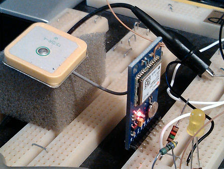
One the left is the receiver undergoing initial tests. You can see the patch antenna on the left raised on a block of foam so that it can "see" past the clutter of the receiver, the receiver itself on the blue PCB mounted vertically in the breadboard, and you might just see the orange-pink wire at the top-right corner of the receiver which has been carefully soldered to pin 3 of the NEO-6M to get the PPS signal. The wire is anchored in the top-right mounting hole for strain relief. You don't need surface-mount tools to make this connection, but you do need a very fine soldering tip and considerable care! Like the TX/RX signals from this module, the PPS signal is at 3.3 V level and therefore ideal for feeding the Raspberry Pi. The board will accept either 3.3 V or 5 V power while retaining 3.3V I/O levels, and I'm using 5 V to power the board to reduce the load on the 3.3 V regulator on the Raspberry Pi board. The U-blox device is specified at less than 50 mA supply current.
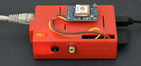
For the final installation, the Adafruit module was used as its single package was more convenient. Not all the leads are connected as there is only one place to connect ground on the module (so the blue is left open), and for simplicity the green Pi Tx => GPS Rx was not connected. Judge the size of the Raspberry Pi by the Ethernet connector on the left!
The next step was to set up the Raspberry Pi to talk to the new module, use serial GPS data via gpsd for the coarse time, and to use its PPS line to provide precise time just as described above. To preset the serial line speed to 9600 at Linux start-up, edit the file /boot/config.txt to include the line:
init_uart_baud=9600
as it says in: http://elinux.org/RPi_config.txt. You can check using the command:
stty -F /dev/ttyAMA0
I found that the speed was already set to 9600 on a recent
Raspberry Pi installed from the NOOBS software. I gather that on a typical Linux system you might use the
command: stty -F /dev/ttyAMA0 9600.
This time , not only were PPS and ground connections required, but also the serial port and the +5 V line, so I used a piece of 6-way ribbon cable to connect between the Raspberry Pi and my serial GPS device. I happened to have a 10-pin header which fitted the GPIO connector, so these are the connections I chose to make:
| My cable |
Raspberry Pi connector |
Comment | GPS module connector |
|---|---|---|---|
| Red | +5V | My unit takes less than 50 mA | 1 +5V |
| +5V | |||
| Blue | Ground | One of two ground connections | 2 GND |
| Green | TXD | Not connected, see below | |
| Yellow | RXD | Receives serial data sent from the GPS | 3 TXD |
| GPIO 18 | |||
| Ground | |||
| GPIO 23 | |||
| White | GPIO 24 | Receives the PPS sent from the GPS | PPS pin on u-blox device |
| Black | Gnd | One of two ground connections | 6 GND |
I actually didn't connect the TXD lead to the GPS module in the first instance,
as the GPS receiver powers up sending data in the correct format, so there is
nothing which the computer needs to control. There is a description
of the GPIO pin header here.
Again, please note that 3.3 V signals are required, not the 5 V level, and
definitely not the RS-232 level!
We need to tell gpsd to look for input from a different source: ttyAMA0 instead of ttyACM0
$ sudo nano /etc/default/gpsd
and change the DEVICES= to point to "/dev/ttyAMA0". You could use "sudo dpkg-reconfigure gpsd" instead. You may also find that the delay between PPS and TXD on the serial line is different from that over USB, so you may wish to edit your ntp.conf accordingly - it makes the output look nicer at least and may make prediction of the nearest second more accurate during the initial acquisition. In my case I needed to change the 0.35 second offset seen in the earlier device to the 0.13 second offset seen with the U-blox device, hence the following change in ntp.conf, from
fudge 127.127.28.0 time1 +0.350 refid SHM stratum 15
to:
fudge 127.127.28.0 time1 +0.130 refid SHM stratum 15
This configuration has been running since Friday, November 09, 2012.
On reflection, I am unsure why I chose to make the stratum 15 in the example above, Possible stratum 2 or 3 might be better, otherwise NTP may think that the source is of very poor quality and fail to sync to it.
Robin Scwab notes that you could try using the value of
"Time offset" displayed in cgps -s as the starting value for the time1
parameter. This sounds to be a gooo idea, except that on one system here I
happened to check Time Offset was about 0.640 seconds, but the best value for
time1 (i.e. the value resulting in the smallest average offset) was 0.130
seconds. Where did the extra 0.5 seconds come from?
Someone asked: "How many NTP clients can it handle?" Well, I have not done any extensive testing on how many clients this NTP server can handle (as it will easily be enough for use on a LAN, and it's not fit for public use in its present security date). I did manage to locate one NTP stress-testing program here, but the maximum rate I could get it to produce on my PC was about 75 packets per second, and the Raspberry Pi can handle that rate with ease. With NTP client PCs polling at 64 second intervals (the fastest normally used), that's 4800 clients, so easily enough for a small organisation. If you were using this for a small organisation, I would recommend using two or three stratum-1 servers so that you are covered in the event of failure - perhaps mark one of the servers "prefer" on the client PCs to avoid NTP from "clock-hopping". If you have better stress-test data, as Kasper Pedersen did, please let me know and I can publish it here.
Kasper Pedersen notes:
I did one a few years ago that goes a bit faster (Linux):
http://n1.taur.dk/permanent/ntpload.c
To test a Raspberry Pi you need 4 instances running, at which point the
Pi runs out of CPU, and settles on 3520/s. That ought to be enough for most small homes.. :-)
These are brief notes only, on an alternative approach which does not require a modified kernel with PPS support in the OS, nor does it require a recompiled NTP, but which produces slightly less accurate timekeeping. It may, however, be quite good enough for most purposes. The program was developed by Folkert van Heusden, see: http://vanheusden.com/time/rpi_gpio_ntp/ and announced in the Time-Nuts mailing list.
You can start here assuming that you have your Raspberry Pi basically working with GPSD and NTP, meaning that:
The objective is to determine the offset between the PPS signal from your GPS and the serial data which typically follows some hundred or more milliseconds later. NTP can use that offset either to make a better sync when using just a GPS receiver with no PPS, or to present a slightly less confusing ntpq -p output when using PPS. To measure what offset should be specified for the time1 factor when using a GPS receiver (type 28 reference clock driver), we can use NTP as a measuring tool by making it sync to existing servers and have it monitor the shared memory #0 written by gpsd. I.e. NTP will not use server 28.0 for timekeeping, but it will display the offset in the ntpq -p command. To do this, you add these lines to your ntp.conf (if they are not already there):
# Server to be monitored only, not selected for syncing
server 127.127.28.0 minpoll 4 maxpoll 4 noselect
fudge 127.127.28.0 time1 0.000 refid GPSD
Watch the results from ntpq -pn, and look at the offset for the server with the refid GPSD. On one of my RPi cards it varied between -322 and -336 (units are ms in the ntpq report). Take an average of those values, and replace the 0.000 after time1 with that average. In this case, the average was -329 ms, so try:
server 127.127.28.0 minpoll 4 maxpoll 4 noselect
fudge 127.127.28.0 time1 0.329 refid GPSD
i.e. if the reported offset is negative, you need to make time1 a positive value. Now you should see much smaller offsets for the GPSD server. It's not essential to do this, but it gives you confidence that things are working as expected, it may help NTP in the early startup, and it produces a less confusing ntpq display. Don't forget to remove the noselect when you have the best value for the offset, and set the flags to include preferred so that NTP knows it can use that source as a seconds provider! There must be at least one prefer for PPS to work. This now has the NTP daemon seeing the GPSD device, and the next step is to add in some PPS support.
server 127.127.28.0 minpoll 4 maxpoll 4 prefer
fudge 127.127.28.0 time1 0.329 refid GPSD
Angelo Mileto writes: What I did to get a good sample of data for the time1 value was let the ntpq -p command run for a period of time and capture the results. Then, using awk, calculate the average/mean of the values collected. If you look at the static ntpq -p output, you will see something like this:
     remote           refid      st t when poll reach   delay   offset  jitter
==============================================================================
 SHM(0)          .GPSD.           2 l   13   16  377    0.000   33.837   3.510
oPPS(0)          .PPS.            2 l   12   32  377    0.000    0.002   0.002
along with other pool/server entries. As noted above, you need to ensure you have a good preferred source for the comparison to work. To capture your data, execute the following at the command line from your user's home directory:
watch -n0.5 "ntpq -pn | grep '.GPSD. 2 1 1' | tee --append GPSD_Offset.txt"
Pay attention to the single and double quotes in that command. If you notice, the grep is looking for the exact line from the ntpq -p output that contains your GPSD refid. So if you named it something different, that would replace the .GPSD. in the command. Also, notice the "2 1 1", that is the stratum, t and when fields. The stratum is whatever you set it to in the ntp.conf; the t should always be a 1 and the when is going to capture the output only when the timer reaches 1 meaning that it just updated the value. There is no sense in capturing data every .5 seconds for data that doesn't change! So the easiest way to get the value to grep for is to manually run the ntpq -p and copy from your refid through the when fields and that's what will be grepped for.
Let that run for a good while - probably not really needed - but that's the point of getting a good sample size. This will capture the output from the ntpq command filtering to just your SHM/GPSD. This will all be saved to a file GPSD_Offset.txt in the current directory - that's what the "tee --append GPSD_Offset.txt" does. You can tail -f that file if you want while the watch command is running to see what is going into that file. NOTE: If you need to restart the process because you changed some setting and want to start over, delete any existing GPSD_Offset.txt file first.
Once you have a sufficient sample size, you can then use the following command to get the actual value for the average/mean:
awk '{total=total+$9; count=count+1} END {print "Total:"total; print "Count:"count; print " Avg:"total/count}' GPSD_Offset.txt
This steps through every line of the GPSD_Offset.txt file and totals up all of the offset values.
It will also count how many lines/values are there. Finally it just prints the information: Total, count and average.
The average value is what you would put into the time1 value as noted above.
Don't forget to change the noselect to prefer when you are in there to add the time1 value.
Angelo Mileto
DJT: This is somewhat beyond my Linux, so my thanks to Angelo for the scripts and the
detailed explanation. Angelo can be contacted here.
As of 2013-Jun-18, rpi_gpio_ntp-0.3 was the current version, but thanks to Thomas Erthner I know that version 1.5 is now available, so I've updated the lines below. However, I've only tested version 0.3, not version 1.5. For more details, please see Folkert's page.
$ wget http://vanheusden. com/time/rpi_gpio_ntp/rpi_gpio _ntp-1.5. tgz $ tar xvfz rpi_gpio_ntp-1.5.tgz $ cd rpi_gpio_ntp-1.5 $ sudo make install
This places the resulting binary in /usr/local/bin/. You don't need this for current Raspbian versions.
$ sudo rpi_gpio_ntp -g 8 -d
rpi_gpio_ntp v0.2, (C) 2013 by folkert@vanheusden.com

NTP unit: 0
GPIO pin: 8
Fudge : 0.000000
"Fork into the background" disabled because of debug mode.
1371475664.752146325] poll() GPIO 8 interrupt occurred
1371475665.000148935] poll() GPIO 8 interrupt occurred
1371475666.000147203] poll() GPIO 8 interrupt occurred
1371475667.000160470] poll() GPIO 8 interrupt occurred
1371475668.000159739] poll() GPIO 8 interrupt occurred
(Ctrl-C pressed)
$
To make NTP read the PPS timings on the GPSD shared memory, we need to use this command to start the program, assuming the PPS signal is being sent to GPIO-8 (physical pin 24 - see here). Use pin 18 is you are using the no-soldering board.
$ sudo rpi_gpio_ntp -N 1 -g 8
and to edit the ntp.conf file, to include the shared memory driver, on section 1 of the GPSD shared memory, replacing the earlier type 22 driver. Add:
server 127.127.28.1 minpoll 4 prefer
fudge 127.127.28.1 refid UPPS
I suggest "UPPS" to show it's user-mode PPS (and not the more accurate Kernel mode). If you want to see the output pulse from the program, you can add the "-p 7" parameter:
sudo rpi_gpio_ntp -N 1 -g 8 -p 7
and you can then use an oscilloscope to compare the time of the PPS rising edge with the toggling line from GPIO pin 7 (connector pin 26). On my system, there was a variable delay of between 270 and 390 microseconds between PPS and program response.
More information to follow, for now, this from Folkert: edit /etc/rc.local and add the following (BEFORE the exit 0 statement and AFTER the #!/bin/sh line):
/usr/local/bin/rpi_gpio_ntp -N 1 -g 8
Replace '8' by the gpio pin you are using, e.g. 18 for the no-soldering board.
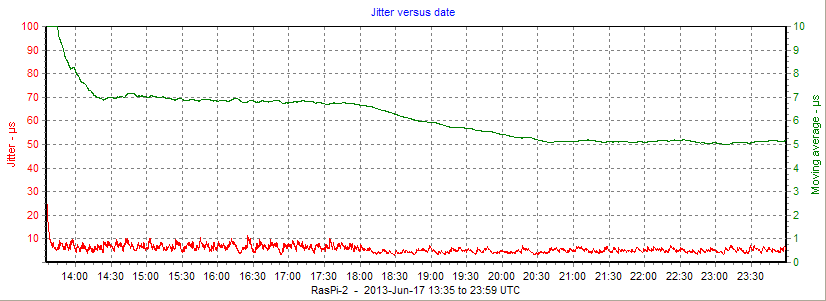
The original documentation suggested using minpoll=1, however on testing using ntpq -pn it appeared that NTP will automatically accept 3 as the minimum value. As the previous testing with kernel-mode PPS had been with minpoll=4, it seemed only fair to test with that value. You can see the change from minpoll=1 to minpoll=4 just after 18:00 UTC. Recall that 1 was replaced internally by 3, the lowest value NTP will accept. With minpoll=4, both the reported offset and the averaged jitter were reduced. First, what it looks like in MRTG for comparison with the results above:
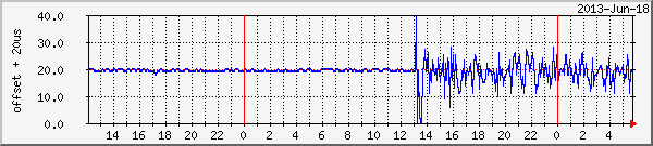
Don't get confused: the MRTG plot above covers rather more than one day, whereas the plots below cover just under half a day. On the plot MRTG plot, you can see that the RPi was changed from kernel-mode PPS at 13:00 UTC and run for a short while with Internet servers alone, visible as the larger excursions on the plot above around 13:00).
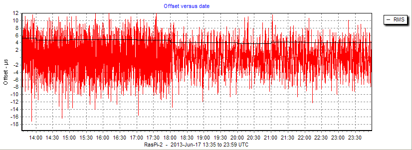
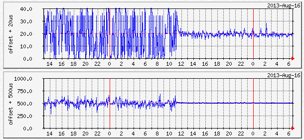
From my NTPplotter program graphs below, you can see more clearly that at 13:30 the user-mode PPS was started, and the just after 18:00 the minpoll was changed from 1 (actually 3) to 4, resulting in a slight drop of RMS offset from around 5 microseconds to 4 microseconds:
The jitter graph shows a drop in averaged jitter (green line) from just below 7 to just above 5 microseconds after 18:00, when the minpoll was changed from 3 to 4. The initial higher value of averaged jitter is the tail resulting from Internet-only sync.
On another Raspberry Pi you can see the dramatic difference between NTP sync over the network and that achieved with the user-mode PPS software. In this case, network sync was to a local NTP stratum-1 server over a Wi-Fi connection, and the PPS sync was with a U-blox 5S module. User-mode PPS was started just after 11:00 UTC in the middle of the graphs below. RMS offset dropped from a rather variable 48-80 microseconds to around 2 microseconds, and jitter averaged over 6 hours dropped from around 80 microseconds to under 2.5 microseconds.
To monitor NTP you can edit the ntp.conf file to turn on the generation
of more detailed statistics data. Note that this data maybe a megabyte or more per day, so think about keeping only a few days
worth, and only enabling statistics collection when needed as the number of
writes to the SD card flash memory is limited. The detailed information
can now be found here and I
offer a program to plot the statistics data and produce offset and jitter graphs
such as those above here.
I may have been unfortunate in locating one Raspberry Pi with an Adafruit module in a position where it was not getting as good a view of the sky as others, or it may be that other devices connected to that RPi or software installed is an issue. I have been seeing transient poor time-keeping (loss of GPS PPS signal) at intermittent times. I did discover that disconnections a lead to a USB hub connected to that RPi seemed to improve things.
If the problem was caused purely by unfortunate GPS satellite position, I might have expected it to repeat in a near 24-hour pattern, which does appear to be the case. Thanks to John Ryan for correcting me about the GPS orbital period, I was originally thinking sidereal time and 4 minute earlier each day. However, on the Time-Nuts mailing list, in connection with another topic, Bob Camp commented:
"The GPS constellation repeats roughly once a day. It is not at all uncommon to have a �worst case� satellite geometry for a given antenna location. If you have one, it will repeat once a day and show up as a bump in the timing out of your GPS module...."
Although the GPS satellites repeat position in just less than 12 hours, there is also the rotation of the earth to take into account, so the position repeats at your location every 24 hours (well, ~23 h 56 m).
On reflection, 2014 February 09, this is the only Raspberry Pi with certain radio software installed, and the problem only seems to occur some days after a reboot, so I think I will stop recording the problem here. I am editing out the transients as they affect the P/N timekeeping graphs, but I leave the raw-graphs as-is.
| Date | Transient |
|---|---|
| Dec 31 | 20:00-20:45, 23:10-24:00 |
| Jan-01 | 20:14-20:37, 23:17-23:28 |
| Jan-02 | 01:29 02:45, 19:57..20:13, 20:14..20:29, 20:31, 23:13, 23:24 23:30..23:54 |
| Jan-03 | 02:39, 03:44, 20:12..20:22, 23:24..23:52 |
| Jan-04 | 02:37, 20:03..20:28, 23:06, 23:41..23:45 |
| Jan-05 | 02:31 |
| Removed USB extension cable from RasPi-2 | |
| Jan-06 | 19:33..1940, 19:54, 22:49..22:55 |
| Jan-10 | 20:30 22:07-22:17 22:37-22:45 23:03 |
| Jan-11 | 21:57-23:18 |
| Jan-12 | 22:01-22:54 |
| Jan-13 | 19:17-19:37 22:37-22:54 |
| Jan-14 | 01:46-01:47 19:30 19:40 22:46-22:51 |
| Jan 15 | 01:47 19:16-19:35 22:42-22:46 23:06 |
| Jan-16 | 19:05-19:32 22:24-22:41 |
| Jan-17 | 19:07-19:19 22:04-22:34 |
| Jan-18 | 19:11-19:16 21:55-21:57 |
| Jan-19 | 02:38-02:39 |
| Jan-20 | 19:04-20:06 |
| Jan-21 | 02:55-03:03 03:17 19:00 19:46 20:15 22:06 |
| Jan-22 | 02:56-03:05 |
| Jan-23 | 10:46 12:48 |
| Jan-24 | 02:48-02:53 07:21 07:44 12:46-12:48 17:11 19:20-19:36 |
| Jan-25 | 07:13 07:18 07:52-07:53 13:02-13:11 |
| Jan-26 | 02:50 03:26 18:06 18:31-18:36 21:59 |
| Jan-27 | 02:42 02:57-03:37 07:09 (reboot at 17:23) |
| Jan-31 | 21:19-21:21 |
| Feb-05 | 20:59 23:12 (is this something which starts days after boot?) |
| Feb-07 | 18:03 18:41 20:52 |
| Feb-08 | 15:09 15:42 18:37 20:33 20:46 21:24 |
| Feb-09 | 00:13 00:37-00:43 01:37 |
If you are operating completely alone, with no internet connection and just the GPS, your NTP may need to be told about leap-seconds which change the offset between GPS time and wall-clock time every so often. Some GPS receivers provide this information automatically, but this can also be done by providing a file with the times of changes (in a standard format) and telling ntpd where to find that file. On my own systems I have set up a Samba share on the NTP servers so that I can update the leap-seconds file from a central location. To do this, add a new writeable share named "ntp-leapseconds" by adding lines to the end of smb.conf, and then restart Samba:
sudo nano /etc/samba/smb.conf[ntp-leapseconds] comment = NTP leapsecond.file path = /home/pi/ntp writeable = yes guest ok = yes sudo /etc/init.d/samba restart
I chose to put my leap-seconds file in the default user's "ntp" home directory, but you may prefer some where more secure! To tell ntpd where to find the file, add one line to the end of ntp.conf with nano, and restart NTP:
sudo nano /etc/ntp.confleapfile /home/pi/ntp/leap-seconds.filesudo /etc/init.d/ntp restart
You can get the leap-seconds file from a variety of locations, including:
ftp://utcnist.colorado.edu/pub/
ftp://tycho.usno.navy.mil/pub/ntp/
and it will be named leap-seconds.3582403200 with a different serial number as the information is updated (this file was found in December 2013). I copy the file to a constant name: leap-seconds.file so that I don't need to alter NTP each time. I then have a small Windows command file to update all my systems - Windows, FreeBSD and Raspberry Pi cards. Here's an extract:
XCOPY /D /Y  leap-seconds.file  \\Alta\ntp\etc\
XCOPY /D /Y  leap-seconds.file  \\Stamsund\ntp\etc\
XCOPY /D /Y  leap-seconds.file  \\Pixie-II\ntp-leapseconds\
XCOPY /D /Y  leap-seconds.file  \\RasPi-1\ntp-leapseconds\
XCOPY /D /Y  leap-seconds.file  \\RasPi-2\ntp-leapseconds\
PAUSE
You can check whether NTP is using the file, and whether your file is stale, with the: ntpq -crv command:
associd=0 status=01fd leap_none, sync_pps, 15 events, kern,
version="ntpd 4.2.7p408@1.2483 Sun Dec 29 14:36:43 UTC 2013 (1)",
processor="armv6l", system="Linux/3.6.11", leap=00, stratum=1,
precision=-19, rootdelay=0.000, rootdisp=1.180, refid=PPS,
reftime=d66b96d3.01b61b26  Mon, Dec 30 2013  6:53:07.006,
clock=d66b96df.3df17b24  Mon, Dec 30 2013  6:53:19.241, peer=61352, tc=4,
mintc=3, offset=0.000281, frequency=-34.180, sys_jitter=0.001907,
clk_jitter=0.001, clk_wander=0.003, tai=35, leapsec=201207010000,
expire=201406010000
Look at the two final lines. leapsec shows the latest leap second (here is was on 2012 Jul 01), and when the leap-second file expires (here: 2014-Jun-01). There will also be a warning if the file is stale.
Update the file from time-to-time - say every six months - in
May and November as leap-second changes usually happen at the end of June or
December. There is more information here.
If you keep getting a different ntp.conf from that which you edited, your router may be the cause. It seems some routers give out NTP information in DHCP which the Pi by default uses over /etc/ntp.conf.
The fix I think is:
rm /etc/dhcp/dhclient-exit-hooks.d/ntp
and if you have the following file, remove it as well:
rm /var/lib/ntp/ntp.conf.dhcp
Then reboot.
You can produce real-time graphs like those below using MRTG and a simple script which can get the statistics from NTP remotely. There is more information here. I happen to run MRTG and the collection scripts on a Windows PC.
RasPi-4 - model 1B
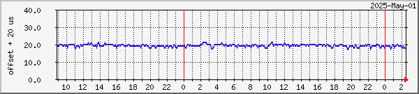
RasPi-25 - model 4B
Information on general SNMP monitoring may now be found here. This allows monitoring of the network I/O on the card, and a number of other parameters which are exposed for measurement by the OS. An example graph follows:
RasPi-3
As NTP tries to keep the clock on the card at a constant frequency, it is often compensating for the effects of temperature changes which cause frequency changes. It is therefore worthwhile monitoring the CPU temperature monitoring as described here, although with a PPS signal and when used as a stratum-1 server, temperature effects may be less obvious. Example graphs are shown below:
RasPi-4
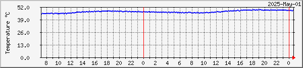
The MRTG monitoring scripts (which I actually run on a Windows PC
covering several Raspberry Pi cards) are in this Zip
archive.
I extended the SNMP pass function to allow monitoring of ambient temperature using the DS18B20 "single-wire" device. This is well written up for use with the Raspberry Pi here, and the detailed description is now here. Sample results:
RasPi-4
Indoor temperature °C Outdoor temperature °F
My thanks to Webshed for
uploading the information about using the DS18B20.
If you are running a server which is accessible from the
public Internet - perhaps you are contributing to the NTP
Pool project - there are some simple precautions you should take to ensure
that your server is not used as the source of an attack on other PCs. Note
that this doesn't apply to most end-user clients sitting on your local PC, you
would need to have specially opened a port in your firewall or router to allow
public incoming unsolicited UDP port 123 packets into your local network.
If you are using a development version (4.2.7p26 or later) you are already
protected. The following notice explains more:
| NTP users are strongly urged to take immediate action to ensure that their NTP daemon is not susceptible to use in a reflected denial-of-service (DRDoS) attack. Please see the NTP Security Notice for vulnerability and mitigation details, and the Network Time Foundation Blog for more information. (January 2014) |
| http://www.ntp.org | The NTP Project Site |
| http://support.ntp.org | The NTP Support Project |
| http://nwtime.org/why-join | Become a supporting member of Network Time Foundation |
| http://nwtime.org/donate | Donations to Network Time Foundation |
| http://www.nwtime.org | The Network Time Foundation main site |
|
|